V4SE and V8SE Enclosures for NonStop S-Series Servers HP Part Number: 545866-001 Published: May 2008 Edition: G06.
© Copyright 2008 Hewlett-Packard Development Company, L.P. Legal Notice Confidential computer software. Valid license from HP required for possession, use or copying. Consistent with FAR 12.211 and 12.212, Commercial Computer Software, Computer Software Documentation, and Technical Data for Commercial Items are licensed to the U.S. Government under vendor’s standard commercial license. The information contained herein is subject to change without notice.
Table of Contents About This Document.........................................................................................................7 Supported Release Version Updates (RVUs)..........................................................................................7 Intended Audience.................................................................................................................................7 New and Changed Information in This Edition.............................................
B Ethernet Connectivity Planning and Configuration Forms........................................21 Safety and Compliance..................................................................................................25 Index.................................................................................................................................
List of Figures 1-1 B-1 V4SE and V8SE Hardware Diagram.............................................................................................10 Completed Ethernet Port Configuration Form ............................................................................
List of Tables 1-1 2-1 4-1 A-1 A-2 A-3 6 V4SE and V8SE Minimum Firmware............................................................................................11 Naming Conventions for V4SE and V8SE Enclosure Components and Related Subystems, Processes, or Devices.....................................................................................................................13 V4SE and V8SE Enclosure LEDs and Their Functions..................................................................
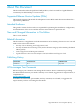
About This Document This document describes the V4SE and V8SE products, which are used for Gigabit Ethernet connectivity for HP NonStop™ S-series servers. Supported Release Version Updates (RVUs) This manual supports G06.24 and all subsequent G-series RVUs until otherwise indicated in a replacement publication. Intended Audience This guide is written for those who are responsible for planning the installation, configuration, and maintenance of the server and the software environment at a particular site.
1 V4SE and V8SE Enclosures Product Overview Two products are available to replace the discontinued single-port Gigabit Ethernet ServerNet Adapter, GESA (3865-C and 3865-F), and in some cases the single-port 100 Mps Ethernet controller, FESA (Fast Ethernet ServerNet Adapter): • V4SE: A Versatile Ethernet ServerNet (VES) enclosure with 4 Ethernet ports, two of which are Gigabit per second Ethernet ports.
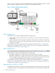
Figure 1-1 (page 10) shows the back of a V8SE enclosure. The ground cable connection, located next to the power supply in slot 18, is not used for AC-powered enclosures. Figure 1-1 V4SE and V8SE Hardware Diagram V4SE Configurations The V4SE uses one of these embedded Ethernet configurations: • • Copper only: In slot 6b, all four ports are used. There is a card in slot 6a/7a, but the ports are not used. Copper and optical: In slot 6b, ports A and B are used but ports C and D are not used.
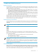
V4SE and V8SE Firmware Table 1-1 V4SE and V8SE Minimum Firmware Product Number Description Filename Default Location T1805AAC Integrated maintenance entity M1805 (IME) firmware for V4SE or V8SE logic board $SYSTEM.SYSnn T0789 Maintenance entity (ME) FPGA firmware for V4SE or V8SE logic board SAM0789 $SYSTEM.SYSnn T0612 G4SA firmware C0612R00 $SYSTEM.SYSnn System Installation Specifications See Appendix A (page 19).
group 14. However, you must have both an X-fabric V4SE or V8SE and a Y-fabric V4SE or V8SE in a group. Both enclosures in the pair must be the same: either V4SE or V8SE. V4SE or V8SE Group-Module-Slot Numbering NOTE: In OSM, the V4SE and V8SE are identified as VIO modules.
2 Factory-Default Naming Conventions HP manufacturing uses a naming convention for processes and devices that relates logical names to the physical location of devices. Table 2-1 Naming Conventions for V4SE and V8SE Enclosure Components and Related Subystems, Processes, or Devices Subsystem, Process, or Device Type Convention Example G4SA Adapter object Ggroup-module-slot $ZZLAN.G4326a G4SA LIF object Lgroup-module-slot-pif $ZZLAN.
n is an alphanumeric value (A through Z or 0 through 9) assigned automatically by the WAN manager process.
3 Configuring the Ethernet Ports The Ethernet ports in V4SE or V8SE enclosures are configured and managed through the Subsystem Control Facility (SCF) interface to the ServerNet LAN Systems Access (SLSA) subsystem. The SLSA subsystem is preinstalled and preconfigured and is started during the system-load sequence. For planning forms, see Appendix B (page 21). For information about the SLSA subsystem, see the LAN Configuration and Management Manual.
7. 8. 9. 10. 16 Disconnect the associated fiber optic cable from slot 7a. Connect an RJ-45 cable to the appropriate copper port at slot 7b. Use the SCF START ADAPTER command to start the copper ports. Use the SCF STATUS ADAPTER command to verify the copper ports are in a STARTED state.
4 Status LEDs Table 4-1 V4SE and V8SE Enclosure LEDs and Their Functions Component LED Indicator State Meaning V4SE or V8SE enclosure Status Green Power is on. Amber A fault exists with a FRU (for example, a hardware error or a FRU reset). ServerNet connection (port 14) Link Status Green Lights during power-on and when a valid link is detected. G4SA (slots 6a/6b/7a/7b)1 Status Green Power is on, and port is available.
A Modular Cabinet and V4SE and V8SE Enclosure Specifications Modular Cabinet Specfications For all information about the modular cabinet, including specifications and site planning requirements, see the NonStop NS14000 Series Planning Guide. V4SE and V8SE Enclosure Specifications Dimensions and Weight Unit Size: 4U (height) Height: 6.9 in (17.5 cm) Width: 19.0 in (48.3 cm) Depth: 29.37 in (74.6 cm) Weight: 68 pounds (31 kilograms) when fully loaded.
Safety: CSA and C/US Certified, complies with EN60950 Ethernet Cable Specifications Table A-3 Ethernet Cable Specifications Port Type Connector Cable Media1 Maximum Distance 10 Base-T (802.3) RJ-45 male Category (CAT) 5, 5e, or 6 unshielded twisted-pair (UTP) cable 100 meters (328 feet) 100 Base-TX (802.3u) RJ-45 male CAT 5, 5e, or 6 UTP cable 100 meters (328 feet) 1000 Base-TX (802.
B Ethernet Connectivity Planning and Configuration Forms Blank Ethernet port planning and configuration forms follow. You should make several copies of these forms when you are adding Ethernet ports to a V4SE or V8SE enclosure. You are authorized to photocopy these forms only for the purpose of installing and configuring your HP system. When you have finished using the Ethernet port planning and configuration forms, place them in your Documentation Packet (if applicable).
Ethernet Connectivity Planning and Configuration Forms
Figure B-1 Completed Ethernet Port Configuration Form 24 Ethernet Connectivity Planning and Configuration Forms
Safety and Compliance This section contains three types of required safety and compliance statements: • • • Regulatory compliance Waste Electrical and Electronic Equipment (WEEE) Safety Regulatory Compliance Statements The following regulatory compliance statements apply to the products documented by this manual. FCC Compliance This equipment has been tested and found to comply with the limits for a Class A digital device, pursuant to part 15 of the FCC Rules.
Taiwan (BSMI) Compliance Japan (VCCI) Compliance This is a Class A product based on the standard or the Voluntary Control Council for Interference by Information Technology Equipment (VCCI). If this equipment is used in a domestic environment, radio disturbance may occur, in which case the user may be required to take corrective actions.
1M Laser Product in accordance with US FDA regulations and the IEC 60825-1. The product does not emit hazardous laser radiation. WARNING: Use the controls or adjustments or performance of procedures other than those specified herein or in the laser product’s installation guide may result in hazardous radiation exposure. To reduce the risk of exposure to hazardous radiation: • LASER RADIATION - DO NOT VIEW DIRECTLY WITH OPTICAL INSTRUMENTS. CLASS 1M LASER PRODUCT. • Do not try to open the module enclosure.
total combined leakage current should not exceed 5 percent of the rated input current for the device. “HIGH LEAKAGE CURRENT, EARTH CONNECTION ESSENTIAL BEFORE CONNECTING SUPPLY” “HOHER ABLEITSTROM. VOR INBETRIEBNAHME UNBEDINGT ERDUNGSVERBINDUNG HERSTELLEN” “COURANT DE FUITE E’LEVE’. RACCORDEMENT A LA TERRE INDISPENSABLE AVANT LE RACCORDEMENT AU RESEAU” FUSE REPLACEMENT CAUTION – For continued protection against risk of fire, replace fuses only with fuses of the same type and the same rating.
Index L LED, functions, 17 LIF, naming convention, 13 LISTNER process, naming convention, 13 S SNMP agent processes, naming convention, 13 SNMP trap multiplexer processes, naming convention, 13 T TCP/IP process, naming convention, 13 TELSERV process, naming convention, 13 TFTP server processes, naming convention, 13 V V4SE and V8SE enclosures configurations of, 10 configuring Ethernet ports, 15 factory-default naming conventions, 13 firmware files, 11 GMS numbering, 12 power connections, 11 required soft