
V4SE and V8SE Enclosures for NonStop S-Series Servers
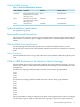
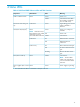


V4SE and V8SE Firmware
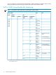
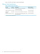
Table 1-1 V4SE and V8SE Minimum Firmware
Default LocationFilenameDescriptionProduct Number
$SYSTEM.SYSnn
M1805Integrated maintenance entity
(IME) firmware for V4SE or
V8SE logic board
T1805AAC
$SYSTEM.SYSnn
SAM0789Maintenance entity (ME)
FPGA firmware for V4SE or
V8SE logic board
T0789
$SYSTEM.SYSnn
C0612R00G4SA firmwareT0612
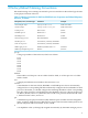
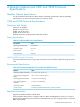
System Installation Specifications
See Appendix A (page 19).
Power and Ground Connections
For the enclosure to operate, at least one power supply in the enclosure must be operational. For
fault tolerance, connect each power supply in the enclosure to a different PDU in the modular
cabinet.
V4SE and V8SE Power Specifications
For site planning information and specifications for V4SE and V8SE enclosures, see the
specifications for VIO enclosures and modular cabinets in the NonStop NS14000 Series Planning
Guide.
Ground Connections
V4SE and V8SE enclosures have ground connections to the modular cabinet through the power
cord.
V4SE or V8SE Enclosures in the Tetra-8 or Tetra-16 Topology
V4SE and V8SE enclosures are supported in both the Tetra-8 and Tetra-16 topologies. You can
install a pair of V4SE or V8SE enclosures anywhere that a NonStop S-series I/O enclosure would
be supported.
For the Tetra-8 topology V4SE and V8SE enclosures can have these group numbers:
11-12
21-22
31-33
41-42
For the Tetra-16 topology V4SE and V8SE enclosures can have these group numbers:
11-15
21-25
31-35
41-45
51-54
61-64
71-74
81-84
The group numbers of V4SE or V8SE enclosure pairs can be assigned in any order. For example,
you can install a pair of V4SE or V8SE enclosures as group 15 even if the system contains no
System Installation Specifications 11