Operations and Administration Guide HP Virtual TapeServer for NonStop Servers Part Number: 514106-006 Product Version: 6.04.01 © 2004 - 2010 Hewlett-Packard All rights reserved No part of this document may be copied in any form or by any means without prior written consent of HP. All drawings, schematics and artwork used in the manufacture of the products described herein are copyrighted.
Contents Preface . . . . . . . . . . . . . . . . . . . . . . . . . . . . . . . . . . . . . . . . . . . . . . . . . . . . . . . . . . . . . . . . . . . . . vii About this guide . . . . . . . . . . . . . . . . . . . . . . . . . . . . . . . . . . . . . . . . . . . . . . . . . . . . . . . . . . . . . vii Audience . . . . . . . . . . . . . . . . . . . . . . . . . . . . . . . . . . . . . . . . . . . . . . . . . . . . . . . . . . . . . . . . . . . vii Typographical conventions . . . . . . . . . . . . . . . . . . .
Managing virtual tapes . . . . . . . . . . . . . . . . . . . . . . . . . . . . . . . . . . . . . . . . . . . . . . . . . . . . . . . Enabling data compression . . . . . . . . . . . . . . . . . . . . . . . . . . . . . . . . . . . . . . . . . . . . . . . . . Creating a single virtual tape . . . . . . . . . . . . . . . . . . . . . . . . . . . . . . . . . . . . . . . . . . . . . . . Creating multiple virtual tapes . . . . . . . . . . . . . . . . . . . . . . . . . . . . . . . . . . . . . . . . . . . . .
11 Using AutoCopy . . . . . . . . . . . . . . . . . . . . . . . . . . . . . . . . . . . . . . . . . . . . . . . . . . . . . . . . . . . . .113 12 Migrating Data to Physical Tape . . . . . . . . . . . . . . . . . . . . . . . . . . . . . . . . . . . . . . . . . . . . . .117 Manually migrating virtual tapes . . . . . . . . . . . . . . . . . . . . . . . . . . . . . . . . . . . . . . . . . . . . . . 118 Automating migration using VTSPolicy . . . . . . . . . . . . . . . . . . . . . . . . . . . . . . . . . . . . .
Log files . . . . . . . . . . . . . . . . . . . . . . . . . . . . . . . . . . . . . . . . . . . . . . . . . . . . . . . . . . . . SCSI converter . . . . . . . . . . . . . . . . . . . . . . . . . . . . . . . . . . . . . . . . . . . . . . . . . . . . . . . . . . External storage or the SAN . . . . . . . . . . . . . . . . . . . . . . . . . . . . . . . . . . . . . . . . . . . . . . . Software features . . . . . . . . . . . . . . . . . . . . . . . . . . . . . . . . . . . . . . . . . . . . . . . . . . . . . . . .
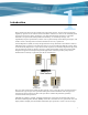
Preface Welcome to the Virtual TapeServer Operations and Administration Guide. This guide provides configuration and day-to-day usage information for Virtual TapeServer (VTS). VTS enables host systems to read from and write to an embedded or attached redundant array of independent disks (RAID). The virtual tape drive emulates the type of tape drive specified during the initial installation and setup process.
Related documentation In addition to this operations and administration guide, refer to the Virtual TapeServer Release Notes, which provides information about system support, known issues, and other information about the current release. Please see your Technical Support representative for a copy of the release notes and for any updated information on the product.
Introduction Tape remains the most practical solution for removable storage, and it is often required by regulatory agencies to be archived and stored offsite. However, as the cost of commodity disk storage has decreased, many enterprises view disk-based backup solutions as a feasible alternative to tape-based backup.
hardware and tape media, automate backup and restore operations, and increase flexibility in managing backed-up data. The virtual environment The basic building blocks of VTS are vaults, pools, virtual tape drives, and virtual tapes. VTS can support multiple virtual tape drives that respond to tape commands just as a physical tape drive would. Virtual pools are organized into vaults, which correspond to areas of the file system that are configured according to user needs.
Overview of features The following VTS features enable you to simplify and streamline tape operations, reduce costs for storage, automate backup and restore operations, and increase flexibility in managing backed-up data: • Flexible and extendable, enabling you to create any number of virtual tape pools that “contain” any number of virtual tapes • Compatibility with Backup, Restore, and TMF • Compatibility with Mediacom and DSM/TC • Support for backup management applications, including IBM Tivoli Sto
• SecureVTS — Encrypts and decrypts backup data written on disk from one or more host servers. Compliance regulations and organizations highly recommend the encryption of valuable data; SecureVTS provides a robust encryption solution that deploys on existing hardware. Industry-standard 256-bit AES symmetric key encryption is used. Overview of the VTS web interface VTS is managed through a standard web browser interface.
EMS — Event Management Service, which starts the EMS distributor on the NonStop server by issuing a Tandem Advanced Command Language (TACL) command. The distributor notifies the VTS EMS service when an EMS message is posted on the NonStop server. VTS — Virtual TapeServer, which refers to the Virtual TapeServer engine and provides the core of VTS functionality. SecureVTS If SecureVTS is enabled, this section displays its status. Free Space Optional section that is shown by default.
• Imports and exports from and to physical drives • Instant DR operations The Virtual Media - Operation page is the homepage, though you can click Virtual Media on the navigation pane to display the Virtual Media - Operation page again. The refresh button at the top of the page enables you to update the information displayed on the Virtual Media page.
contents of the pool. Click the - symbol to collapse the pool. The colors have the following meaning: • Orange — Locked (mounted, Instant DR, migration, AutoCopy, export, or import) • Purple — Autoloading enabled • Red — Remotely addressed • Black — Available If you select an option from the window drop-down list, additional pages are available. You must have the corresponding right(s) to view the pages.
System Overview page When you click View Configurations on the navigation pane, the following page is displayed. The View/Manage Configuration access right is required to view this page. This page lists the virtual-to-physical mappings for the VTS system. It also lists the virtual, logical, and physical tapes that are available to be mapped.
Manage Tape Connections page This page enables you to access other pages to manage virtual tape connections, logical tapes, virtual tapes, and tape definitions. Click Manage Connections on the navigation pane to display this page. The View/Manage Configuration access right is required to view this page.
Supervisory Functions page Click Supervisor Functions on the navigation pane to display this page. The options displayed on this page are based on your access rights; at a minimum, the Supervisory Functions access right is required. Clicking a link on the Supervisory Functions page enables you to perform administrative operations, such as applying updates, editing the configuration file, rebooting the system, downloading files, starting and stopping processes, and examining log files.
Access Control page When you click Access Control on the navigation pane, the Access Control page is displayed. The System Access Controls or User Access Controls access right is required to view this page. If you have the System Access Controls right, this page enables you to grant or limit access to specific VTS functions by managing users and groups. Otherwise, this page enables you to change your password.
Factory Setup page If the Factory Setup option is available, you can click it to display the Factory Setup page: This page enables you to configure VTS and perform administrative functions, such as adding virtual tapes or backing up files. You must have authorized credentials to access this page.
Backing Up the VTS Server It is recommended that you back up the VTS server after any major operation, such as an upgrade. The following steps describe how to create a system restore image, which saves the following: • All databases • root and bill home directories • Some contents of the /etc and /usr/local/tape/etc directories To create a system restore image 1. Make sure VTS is not in use and that no virtual tapes are mounted. 2. Back up the VTS server, as follows: a.
b. Click Create VTS system restore image. The Creating System Restore Image page is displayed. c. When prompted, choose to save the .tgz file. 3. If SecureVTS is enabled, back up the most current backup of the key database by completing these steps: a. Log in to the VTS server as root. b. Use the su command to change to the bill user: su - bill c.
Modifying Virtual Tape Drives You may need to modify one or more virtual tape drives, particularly those that were preconfigured on VTS. You may need to rename virtual tape drives according to your chosen naming convention. This section describes how to modify virtual tape drive properties. Note If you delete the virtual tape drive, you must restart the TapeServer service. When adding or modifying a virtual tape drive in VTS, you must define its properties.
The first four properties are collectively referred to as the BTLI of the virtual tape drive. The BTLI enables the host server to precisely identify the virtual tape connection; it provides an exact address of the virtual tape’s location on the bus. Remember that the host is connected to VTS by a single cable. The BTLI thereby enables you to multiplex the cable (for hosts connected to VTS by a Fibre Channel cable), to identify multiple (virtual) tapes over a single Fibre Channel cable.
The following steps describe how to disassociate the virtual tape drive ($VTAPE01 in this example) from its logical and physical drives (LTAPE01 and PTAPE01): a. In the navigation pane, click Manage Connections. The Manage Tape Connections page is displayed: b. Click Delete a tape connection.
c. Select the connection you want to delete and click Delete Tape Connection. You can verify that the connection was deleted on the following pages: • Virtual Media — Click Virtual Media in the navigation pane and confirm that the virtual tape drive is no longer listed in the table on the page.
The appropriate ID value depends on the host server: • For NonStop S-series servers IDs 4 and 5 are reserved for tape devices, while other IDs are reserved for other device types. NonStop S servers default to target ID 5 for tape drives, therefore it is recommended that you select 5 from the target drop-down list. You can select 4 as the target ID but you must configure the NonStop S server by specifying “DEVICEID 4” with the SCF ADD TAPE command.
j. Specify the host, or initiator, type by choosing an option from the host_type dropdown list. This property is for reference only; it is not presented to the host. This property also specifies the icon selected for the virtual tape on the interface pages. k. In the serial_number field, specify the serial number of your virtual tape. You can specify up to 10 alphanumeric characters. This string is presented to the host and should be unique (across all VTS servers and VTDs in the environment).
Configuring Access Control If you have system administrator privileges, you can configure access control to grant or limit access to specific VTS functions. Each login ID belongs to a group and each group has a unique set of privileges. Note VTS provides a user that has administrator privileges. You can log in as admin if no other administrative user is created on the system. The default password for this user is virtual.
Enabling a closed system You can enable a closed system to require authentication. The user can access only the resources assigned to a particular group. You can enable or disable individual rights to resources. Requires the System Access Controls access right To enable a closed system 1. Click Access Control on the navigation pane. 2. When prompted, log in. After logging in, the Access Control page is displayed. 3.
subcategories are granted by default, though you can remove individual rights in the subcategories.
Rights Administration Group Operations Group Supervisor Group Virtual Tape Mounts and Locks X X Virtual Tape Pool Maintenance X X Erase Cartridges X X HSM Migration X X Mount Cartridges X X Unmount Cartridges X X View System Status X X X Change Refresh Rate X Stop and Start TapeServer X X X X X X X X X Vault Access Access to All Vaults X Note that, by default, the Factory Setup Activities access right is not assigned to any group.
Managing users You can add users to VTS or modify settings of an existing user. The following sections describe how to create, modify, and delete users. Note In the following procedures, if the Users and Groups and Rights sections of the Access Control page are not available, you must enable a closed system. These sections are not displayed if the system is configured as open access. Creating a user Requires the System Access Controls access right To create a user 1.
3. Click + to expand Users and Groups. 4. Click ADD. The name and password fields are displayed. 5. Type a username in the name field. Usernames cannot contain spaces and cannot duplicate existing usernames, group names, or reserved names. Also, they must be alphanumeric, though they can include an _ (underscore) character. 6. Type a password in the password field.
7. Click APPLY. The user is added and additional buttons are displayed. 8. To assign the user to a group, click CHANGE GROUP. The Group drop-down list is displayed. Note The user cannot perform functions until you assign the user to a group. 9. Select a group from the drop-down list and click APPLY.
Changing any user’s password It is highly recommended that you change the passwords of the default users. Requires the System Access Controls access right to change any user’s password To change a user’s password 1. Click Access Control on the navigation pane. 2. When prompted, log in. After logging in, the Access Control page is displayed.
3. Click + to expand Users and Groups. 4. Select the user from the Users drop-down list. 5. Click SET PASSWORD. The Password field is displayed. 6. Type a new password in the field. 7. Click APPLY.
Changing your password Requires the User Access Controls access right to change your password only To change your own password 1. Click Access Control on the navigation pane. 2. When prompted, log in. After logging in, the User Access Control page is displayed. 3. Type your current password in the Old password field. 4. Type a new password in the New Password field. 5. Type the new password again in the New Password (again) field. 6. Click APPLY.
Assigning a user to a group Requires the System Access Controls access right To assign a user to a group 1. Click Access Control on the navigation pane. 2. When prompted, log in. After logging in, the Access Control page is displayed. 3. Click + to expand Users and Groups.
4. Select the user from the Users drop-down list. The SET PASSWORD and CHANGE GROUP buttons are displayed. 5. To assign the user to a group, click CHANGE GROUP. 6. Select a group from the drop-down list and click APPLY. Deleting a user Requires the System Access Controls access right To delete a user 1. Click Access Control on the navigation pane. 2. When prompted, log in. After logging in, the Access Control page is displayed.
3. Click + to expand Users and Groups. 4. Select the user from the Users drop-down list. 5. Click REMOVE. 6. When prompted, click OK to confirm that you want to remove the selected user.
Configuring groups Groups define the access rights that are assigned to users. Three groups are provided: Administration, Operations, and Supervisor. For a list of the default rights assigned to these groups, see page 22. You can modify the access rights that are assigned to these groups. You can also save your changes as a set of custom defaults, which can be restored later if necessary.
3. Click + to expand Rights. 4. To modify access rights assigned to the Administration group, select the checkbox next to each access right in the Administration column. Note The rights are organized in categories. If you grant access to a category, all rights in the subcategories are granted by default, though you can remove individual rights in the subcategories.
Right User Access Controls Description Enables the user to change his or her password only within Access Control Block and Unblock TapeServer Displays the Block & Unblock TapeServer link on Supervisory Functions page, which enables the user to block and unblock VTS functions Database Download Enables the user to download the database from the Supervisory Functions page Database Upload Enables the user to upload a database from the Supervisory Functions page Edit VTS Configuration File Enables the u
Right Description Scan and Cleanup Control Panel Grants access to the Virtual Media - Scan/ Cleanup page Virtual Tape Cartridge Maintenance Grants access to the Virtual Media - Cartridge Maintenance page Delete Cartridges Enables the user to delete virtual tapes from the Virtual Media - Operation and Virtual Media - Cartridge Maintenance pages Virtual Tape Import and Export Grants access to the Virtual Media - Import/ Export page Virtual Tape Instant DR Grants access to the Virtual Media - Instan
5. To modify access rights assigned to the Operations group, select the checkbox next to each access right in the Operations column. See step 4 for a description of each right. 6. To modify access rights assigned to the Supervisor group, select the checkbox next to each access right in the Supervisor column. See step 4 for a description of each right. 7. Click APPLY above the table to save your changes.
2. When prompted, click OK to confirm that you want to save the settings as the custom defaults. The Restore CUSTOM Defaults button becomes available in the Defaults and Undo section of the page. To restore the custom default settings Click the Restore CUSTOM Defaults button to restore the custom configuration and discard changes made since the custom defaults were last saved.
40 | Configuring Access Control
Configuring EMS Communication To automate the process of mounting and dismounting virtual tapes, you must configure the Event Management System (EMS) on Virtual TapeServer (VTS). The EMS service starts the EMS distributor on the NonStop server by issuing a Tandem Advanced Command Language (TACL) command. The distributor notifies the VTS EMS service when an EMS message is posted on the NonStop server.
Parameter Description Values Required ems_notify_enable Enables EMS messages to be generated for notifications. YES or NO No YES or NO No ALL, INFO, WARNING, ERROR, CRITICAL, or NONE No List of hostnames or IP addresses separated by spaces No Default value: NO ems_notification_ enable Enables VTS to send notification messages back to the NonStop host from EMS messages.
Parameter Description Values Required ems_keep_alive Specifies the number of seconds between periodic EMS messages that are sent from VTS to the host so that the Telnet session does not time out. When set, EMS filtering on the host can be increased because the Telnet connection between the VTS server and the NonStop host stays alive. If omitted or set to 0, keep-alive messaging is disabled.
Parameter Description Values Required ems_response_ timeout Specifies the timeout value (in seconds) used to wait for each response during the EMS Telnet login process. Integer No Note that you can specify the ems_response_timeout_ NSserver instead of or in addition to this parameter. If ems_response_timeout_ NSserver is specified, its value overrides the value of this parameter for the specified host. See the next step for more information about ems_ response_timeout_NSserver.
Parameter Description Values Required ems_service_ prompt_type Specifies the service selection prompt to which the EMS login process responds and begins. Expression No Expression No Expression Yes Expression No type is the hostname of the NonStop server or TYPE:choice, where choice is the login service, such as TACL, TACLS, XYGATE, or SAFEGUARD. You can also specify _ANYSYS instead of _type.
Parameter Description Values Required ems_login_ useranswer_type Defines the user response shown during the login process. See ems_service_prompt _type for an explanation of type. Expression No Expression No Expression No Default values: • for _TYPE:TACL: logon %username% • for _TYPE:TACLS: %username% • for _TYPE:XYGATE: logon %username% • for _TYPE:SAFEGUARD: logon %username% ems_login_ passprompt_type Defines the password prompt during the login process.
Parameter Description Values Required ems_login_ successful_type Defines a command string to send after successful login. See ems_service_prompt_type for an explanation of type. Expression or null No Default values: • for _TYPE:TACL: /Last Logon:/ • for _TYPE:TACLS: /Last Logon:/ • for _TYPE:XYGATE: /Last Logon:/ • for _TYPE:SAFEGUARD: /Last Logon:/ d. For each hostname specified by ems_hostnames, you can add the following hostspecific EMS parameters at the bottom of the file that is displayed.
Parameter Description Values Required ems_virtdevs_ NSserver Specifies the list of virtual tape drives known to the NonStop server that correspond to the list specified by ems_hostdevs_NSserver. If this entry is omitted, VTS uses the same names listed for the host. If specified, there must be the same number of virtual tape names as host tape names. There is a one-to-one correspondence.
Parameter Description Values Required ems_login_ command_NSserver Initiates the EMS Distributor on the NonStop server. The name variable in the command ($VTMS1 in the following example) should be unique for every VTS server.
ems_hostdevs_DEV2='$TAPE25' ems_virtdevs_DEV2='VTAPE25' ems_service_select_DEV2='TACL' ems_login_command_DEV2='#SET #INFORMAT TACL |EMSDIST /CPU 0, PRI 100, NAME $VTMS1, TERM $ZHOME/ BACKUP 1, TYPE P, COLLECTOR $0, TEXTOUT [#MYTERM]' Here is an example of the parameters set in the default VTS configuration file: ems_enable='NO' ems_mount_delay='0' ems_notify_enable='NO' ems_notification_enable='NO' ems_notification_level='ERROR CRITICAL' ems_keep_alive='YES' ems_notify_hostnames='' ems_notify_wait_timeout='
3. Set the username and password for each EMS host: a. Click Supervisor Functions on the navigation pane. b. Click Manage Passwords. The following page is displayed: c. From the drop-down list, select the EMS host. Note If the EMS hostnames are not in the list, the ems_enable parameter may not be set to YES. d. In the Username field, type a username for that host. e. In the New Password field, type a password for the user. f. Retype the password in the New Password (again) field. g. Click Update. h.
• The recommended action to take. Message Text Severity Recommended Action (Error:) Non-zero return-code ($rc) from dsmc (try this url … for $cart_request. Critical An IBM Tivoli Storage Manager (TSM) failure occurred. Examine the return error code and correct the problem. AUTOCOPY FAILED: Request by: $requestor ($retry_number) cannot create directory $target (rc=$rc) Critical No action is required. The task will be retried.
Message Text Severity Recommended Action Error: BEX $policy $cart_request failed with result code $rc Critical See the HSM get or HSM put log files on the Supervisory Functions page for details about the HSM request. Error: BEX command failure! Critical A syntax error occurred in the BEX command. Repair the request and resubmit. Error: can not determine the proper command for this request. Critical HSM restore for TSM was unable to determine the proper restore or retrieve command.
Message Text Severity Error: Non-zero return-code ($rc) from NetBackup for $cart_request. Warning Error: Processing failed, no files processed for $cart_request Critical No files were successfully processed. See the HSM get or HSM put log files on the Supervisory Functions page for details about the HSM request. Error: Success message not found in NetBackup job output for $cart_request. Critical An HSM request failed to find or process the virtual tapes for the request.
Message Text Severity Recommended Action Info: $jobname ENDED to $backupSystem Inform Info: AUTOCOPY $requestor $source $target ($retry_number) Inform Info: AUTOCOPY Complete $requestor $source $target $retry Inform Info: autocopy from $source to $host:$destination Inform Info: cancel mount of $tape Inform Info: TMFcopy of $tape Inform Non-zero return-code ($rc) from NetBackup bprestore Warning Restored $count file(s) Inform Restored $count file(s), rc=$rc Inform vtape_ems.
56 | Configuring EMS Communication
Configuring User Interface Preferences This chapter describes how to configure user interface preferences by setting parameters in the configuration file and how to set the refresh rate of the System Status page. Enabling features on the user interface You can set a number of parameters in the VTS configuration file to specify the following: • Whether to display the buttons and features on the Virtual Media - Operation page. • Whether and how often to display status messages at the top of the page.
Parameter Description Values opwin_Delete Displays the Delete button on the Virtual Media - Operation page. YES or NO Default value: YES opwin_ImportExport Displays the Import/Export button on the Virtual Media - Operation page. YES or NO Default value: YES opwin_Migrate Displays the Migrate button on the Virtual Media - Operation page. YES or NO Default value: YES opwin_AllowAutoRefresh Whether to allow auto-refresh on the Virtual Media - Operation page.
Parameter Description Values lowspace_notify Enables notification on low vault space. YES or NO Default value: YES lowspace_notify_keep Specifies whether to continue to display the low vault space notification until it is no longer valid. YES or NO Default value: NO lowspace_notify_ percentage Specifies the percentage of free space that must be available; if the amount of free space falls below this percentage, the low vault space notification is posted on the System Status page.
Setting the refresh rate The System Status page is refreshed every 15 seconds by default. Requires the Change Refresh Rate access right To configure the refresh rate 1. Click System Status on the navigation pane. 2. Click the Change Rate button at the bottom of the page. The following page is displayed: 3. Click one of the buttons or specify a value (in seconds) in the field and click the Set Refresh Rate button. 4. Click OK to return to the System Status page.
Managing Pools and Virtual Tapes Virtual TapeServer (VTS) organizes data in vaults, which in turn contain pools. The pools contain virtual tapes. Vaults are defined for you based on your input by the onsite Integration Engineer. This chapter describes how to create and modify pools and virtual tapes. It also describes how to erase, delete, import, and export virtual tapes. Managing pools This section describes how to create and modify pools on the Pool Maintenance page.
3. Select a vault from the VAULT drop-down list. 4. Enter a name for the NEW POOL field. Specify a name that is up to 255 alphanumeric characters in length. Note The pool name must be unique across all vaults on the VTS server. 5. To set a size limit on the pool, deselect the Cartridge Size unlimited checkbox and enter a size (1 - 1023) in the field. Select Megabytes, Gigabytes, or Terabytes from the drop-down list. This sets a maximum size for the virtual tapes in the pool.
9. If the SecureVTS feature is enabled, you can select the Encrypted checkbox to encrypt all cartridges that are added to the pool. See Using SecureVTS on page 81 for more information about this feature. 10. Click the CREATE button. You can click the pool drop-down list to confirm that the pool was created. When you return to the Virtual Media - Operation page, the new pool is listed and a red dot is displayed to the left of its name.
Gigabytes, or Terabytes from the drop-down list. This sets a maximum size for the virtual tapes in the pool. Note If you select the Cartridge Size unlimited checkbox, VTS can create virtual tapes up to 2TB. However, virtual tape sizes may still be limited due to file-system constraints. 7. If you want to set a limit to how long the virtual tapes in the pool are stored, deselect the Retention unlimited checkbox and specify a value in the field.
Deleting a pool When you delete a pool, all virtual tapes in the pool are also deleted. Requires the Virtual Tape Pool Maintenance, Vault Access, and Access to all Vaults access rights; if the pool contains encrypted tapes, the user must also be a member of the Administration group To delete a pool 1. Click Virtual Media on the navigation pane. 2. Select pool maintenance from the window drop-down list at the top of the Virtual Media - Operation page. The Virtual Media - Pool Maintenance page is displayed.
Managing virtual tapes You must create a virtual tape before the NonStop server can mount and write data to it. When you create a virtual tape, a file is created on the VTS server’s disk.
Creating a single virtual tape Requires the Virtual Tape Cartridge Maintenance, Vault Access, and Access to all Vaults access rights To create a virtual tape within a pool 1. Click Virtual Media on the navigation pane. 2. Select cartridge maintenance from the window drop-down list at the top of the Virtual Media - Operation page. The Virtual Media - Cartridge Maintenance page is displayed. 3. Select a pool from the Pool drop-down list. This is the pool in which the virtual tape will be created. 4.
Creating multiple virtual tapes Requires the Virtual Tape Cartridge Maintenance, Vault Access, and Access to all Vaults access rights To create multiple virtual tapes at once 1. Click Virtual Media on the navigation pane. 2. Select cartridge maintenance from the window drop-down list at the top of the Virtual Media - Operation page. The Virtual Media - Cartridge Maintenance page is displayed. 3. Select a pool from the Pool drop-down list. This is the pool in which the virtual tapes will be created. 4.
tape creation error is encountered. This may result in a partial, non-contiguous set of tapes. However, a message is displayed indicating how many tapes were created. 8. Click CREATE. Note The names applied to virtual tapes are not tape labels. They are equivalent to the stick-on labels applied to physical tapes. When you return to the primary operation screen, + is displayed next to the pool indicating that it now contains virtual tapes. Mounting a virtual tape You can manually mount a virtual tape.
4. Click Mount. The following dialog box is displayed. Note If the Mount button is not displayed, see Enabling features on the user interface on page 57 for information about displaying this button. Also, if you cannot click the Mount button, maximize your browser; this should display an arrow cursor and enable you to click the button. See the Release Notes for more information. 5. Click OK to mount the virtual tape for read and write operations. Click Cancel for read operations only.
Erasing and deleting virtual tapes You can erase the contents of a virtual tape or remove the tape altogether. To perform these operations, you must unmount the virtual tape first, if it is mounted. The following sections describe how to manually erase and delete a single tape or multiple tapes. You can also automate these operations from the NonStop server using the VTSPolicy command if Event Management Service communication is configured. (See Configuring EMS Communication on page 41.
2. Select a virtual tape in the cartridge column. You may need to expand a pool to see the list of virtual tapes. 3. Click Erase to erase the contents or click Delete to delete the entire tape. Note If the Erase or Delete button is not displayed, see Enabling features on the user interface on page 57 for information about displaying these buttons. 4. When prompted, click OK to confirm the operation. To erase or delete a virtual tape from the Cartridge Maintenance page 1.
Multiple virtual tapes You can erase or delete multiple virtual tapes from the Virtual Media - Cartridge Maintenance page only.
7. Select the Override checkbox to perform the operation for the specified range of virtual tapes even if some virtual tapes do not exist in that range. This checkbox forces VTS to delete the virtual tapes even if some do not exist in the range. 8. Click ERASE or DELETE. 9. When prompted, click OK to confirm the operation. Automation using VTSPolicy commands The VTSPolicy command enables you to automatically erase or delete specific virtual tapes directly from a NonStop server.
Here is an explanation of the lines: #SET collector $0 Refers to the EMS collector to which to send the message. Change collector to the name of the collector in the EMS configuration settings on VTS. #SET evt_num number Assigns a number to the event. #SET action -1 Refers to the way the message is displayed in an EMS viewer, such as ViewPoint. In this case, it is inverse text until acknowledged. #SET emphasis -1 Refers to the way the message is displayed in an EMS viewer, such as ViewPoint.
physical tape. When you export a virtual tape, VTS transfers the data to the attached drive or autoloader as if the data was being transferred by the host server. All metadata, files, and file marks are transferred to physical tape, though not in the VTS format. The format of the physical tape is that of the host that originally transferred the data to VTS, where it was stored as a virtual tape. If you export a pool, you can only import the tape(s) back into VTS.
3. Click Import/Export. Or, if SecureVTS is enabled and the tape is encrypted, click Import/Decrypt&Export. The Virtual Media - Import/Export page is displayed. If one or more physical tape drives are connected to VTS, they are detected automatically. (If a physical tape drive is not listed, such as if it was connected after VTS was booted, you may need to rescan the SCSI controllers. See Common issues on page 148 for more information.
Requires the Virtual Tape Import and Export, Vault Access, and Access to all Vaults access rights To import a physical tape Note that you must select a virtual tape to which the data on the physical tape is imported. If data exists on the selected virtual tape, it is overwritten when the data is imported. 1. Click Virtual Media on the navigation pane. The Virtual Media - Operation page is displayed. 2. Select a pool in the pool column. Or, expand a pool and select a virtual tape in the cartridge column.
3. Click Import/Export. Or, if SecureVTS is enabled and the tape is encrypted, click Import/Decrypt&Export. The Virtual Media - Import/Export page is displayed. If one or more physical tape drives are connected to VTS, they are detected automatically. Note If the Import/Export button is not displayed, see Enabling features on the user interface on page 57 for information about displaying this button. 4. Click IMPORT. 5.
Verifying virtual tapes are available from NonStop server To verify that a tape is available on VTS, check the virtual tape size on the Virtual Media Operation page. The size(MB) column indicates whether a tape is unlabeled (empty) or labeled (0). It also indicates the data capacity that is used after a backup runs. (If a labeled tape is erased, the value in this column returns to 0.) If you click the link, a pop-up dialog box is displayed listing tape data. Remember that the size is compressed.
Using SecureVTS SecureVTS is an optional Virtual TapeServer (VTS) software module that enables VTS to encrypt data that is stored on virtual tape. SecureVTS encrypts data when storing it on a virtual tape. Here is how SecureVTS affects tape operations: • When an encrypted tape is mounted, the data that is written to the tape is encrypted. You can also instruct SecureVTS to encrypt data that is already stored on a virtual tape if the tape is not encrypted.
Encryption and decryption during virtual tape operations A virtual tape can be encrypted in several ways: • It can be encrypted when it is created. • It can be manually encrypted after it is created. • It can be automatically encrypted when it is added to a pool that is designated as encrypted. • It can be encrypted if the pool in which it resides is designated as encrypted. Similarly, a virtual tape can be decrypted manually or when its pool is decrypted.
Multi-server considerations Keep the following in mind when configuring and using SecureVTS in an environment with multiple VTS servers, such as if GFS, AutoCopy, or Instant DR is configured: • SecureVTS configuration When configuring key servers and backup hosts for SecureVTS, it is highly recommended that you configure only one key generator for the environment. You must also configure at least one other server in the environment that can serve as the backup host for the key database.
If three VTS servers — A, B, and C — are installed in your environment, you must perform these tasks to fully enable and configure SecureVTS: 1. Determine which server will be responsible for generating keys. For this example, server A will be the “key generator”. 2. Add server A as a key generator on servers B and C. 3. On servers B and C, remove the localhost key server. (The localhost entry is configured as a key generator.) 4.
Prerequisites for configuration Before you begin, you may want to gather the following information to expedite the configuration process: • Username and password of a VTS user account that belongs to the Administration group. • If multiple VTS servers are installed, gather the following: • Hostname or IP address, username, and password of the VTS server that will be configured as the key generator, which will generate keys when virtual tapes and pools need to be encrypted and decrypted.
3. Click ADD NEW SERVER in the KEY SERVERS section of the page. The following is displayed: 4. In the Host/IP Address field, type the hostname or IP address of a VTS server in your environment that you would like to designate as a key server. 5. In the Port Number field, type the port number of the key server, which is 9090 by default. 6. Select the Key Generator checkbox to enable the key server to generate keys.
When you add a backup host, VTS immediately sends a copy of the local key database to the host. This tests the connection to the host and validates the host parameters that you specified. If a copy of the key database exists on the target host, it is overwritten. Note You cannot modify a key database backup host after it is added. To change the settings of a backup host, you must delete it and then add it again, specifying the correct parameters.
Encrypting and decrypting virtual tapes After SecureVTS is enabled and configured, you can encrypt virtual tapes. You can encrypt virtual tapes individually or you can encrypt a pool, which instructs VTS to automatically encrypt virtual tapes when they are added to the pool. • If you encrypt a pool, all virtual tapes in the pool are encrypted when they are created. • If virtual tapes exist in a pool before the pool is encrypted, you can choose whether to encrypt the existing virtual tapes.
5. Select the Encrypted checkbox. (This option is not available if you have not enabled SecureVTS, if you have not logged in, or if you select a vault.) 6. When prompted, click OK to confirm that you want to encrypt all virtual tapes that currently reside in the pool plus tapes that are added to the pool. Or, click Cancel to encrypt only virtual tapes that are added to the pool. 7. Click APPLY on the Virtual Media - Pool Maintenance page.
Decrypting a pool When you decrypt a pool, you are prompted to decrypt all virtual tapes in the pool. After decrypting the pool, virtual tapes are no longer encrypted when they are added to the pool. Requires Administration group membership To decrypt all virtual tapes in a pool 1. Click Virtual Media on the navigation pane. 2. If prompted, log in using an account that is a member of the Administration group. Click the Log In button at the top of the page and enter a username and password. 3.
Managing the SecureVTS configuration You may need to remove a server from the SecureVTS configuration, or you may need to manually backup or restore a key database. The following sections describe how to perform these tasks. Managing licensing After you initially enable licensing, you can update the license key or remove it. Obtain the SecureVTS license key from your Sales representative. To update the license key 1.
3. Click Manage System Licenses. 4. Click REMOVE next to the Secure VTS Key. 5. On the pop-up dialog, click OK to confirm that you want to remove the key. Restoring a key database You can restore a key database, such as if you are reinstalling a server. You can restore a key database from one of the backup hosts listed on the SecureVTS page, which overwrites the localhost’s key database with the most recent backup on the selected backup host.
3. Click the Restore from Disaster Recovery Site button in the KEY DATABASE BACKUP/RESTORE HOSTS section of the page. The following is displayed: 4. In the Host/IP Address field, type the hostname or IP address of the remote server from which VTS will retrieve the key database. 5. In the Username field, type the username of a user account that can access the SCP program on the specified server. 6. Type the password of the user account in the Password field. 7.
5. Re-add the key server(s) as described in Adding a key server on page 85. This ensures that the key servers are created with the current server’s credentials. 6. Re-add the key database backup host(s) as described in Adding a key database backup host on page 86. Backing up a key database Each key server automatically backs up its key database when a new key is generated. However, you can manually back up a key database. Requires Administration group membership To manually backup a key database 1.
Deleting a key database backup host You can remove a backup host so that the key server no longer backs up its database to that server. Note You cannot modify a key database backup host. To change the settings of a backup host, you must delete it and then add it again, specifying the correct parameters. Requires Administration group membership To delete a backup host 1. Click SecureVTS Setup on the navigation pane. 2. If necessary, log in using an account that is a member of the Administration group.
96 | Using SecureVTS
Using Scan/Cleanup Scan/Cleanup is a Virtual TapeServer (VTS) feature that is designed to help you maintain VTS. It scans pools and virtual tapes to identify virtual tapes that are past their retention period. Scan/Cleanup can erase old virtual tapes to recover disk space. You can also schedule virtual tape erasures when the overall disk space falls below a specified threshold. Scan/ Cleanup can be used to erase tapes after migration.
Enabling and configuring Scan/Cleanup You must modify the VTS configuration file to enable Scan/Cleanup and configure some of the business rules. Requires the Edit VTS Configuration File access right To configure Scan/Cleanup Note A default configuration file is defined for each VTS server. To override the default settings, you must define settings as described below. 1. Click Supervisor Functions on the navigation pane. 2. Click Edit VTS Configuration File. 3.
Parameter Description Values cleanup_scan_at Specifies when the automated scan and erasure should run. A typical setting would be 04:30, which indicates to run at 4:30AM. To avoid scheduling problems, set this parameter greater than 00:04 and less than 23:51. Specify 00:00 to disable this feature. Scheduling this once or twice a day should be frequent enough to manage disk space utilization.
Parameter Description Values cleanup_minimum_size_ GB Define which files to ignore based on size. The values specified by these parameters are combined to set the minimum file size to erase. Some installations have many small virtual tapes and do not require that they be erased. A typical setting for the cleanup_minimum_size_GB parameter is 8, which specifies not to erase virtual tapes whose data is less than 8GB. For smaller sizes, use the cleanup_minimum_size_ MB parameter only.
Defaults for these user-defined control parameters are as follows: cleanup_enable='NO' cleanup_show_NO='NO' cleanup_scan_at='00:00' cleanup_interval='24' cleanup_autoerase='NO' cleanup_nonMigrated='NO' cleanup_minimum_size_GB='0' cleanup_minimum_size_MB='0' cleanup_show_erase_column='NO' cleanup_threshold_percent='90' cleanup_show_erase_control_files='NO' cleanup_show_size_column='NO' meta_control_panel='NO' Here is a sample configuration: cleanup_enable='YES' cleanup_show_NO='NO' cleanup_scan_at='00:00' cl
Overview of the Scan/Cleanup page After you enable Scan/Cleanup, you can display the user interface for this feature by clicking Virtual Media on the navigation pane. Then, select scan/cleanup from the window dropdown list. The Scan/Cleanup page is displayed. Here is a description of the status tables, fields, and buttons on this page: Status table This table lists all virtual tapes on the system and their Scan/Cleanup status.
Size Displays the size of the virtual tape (in bytes). This reflects the size of the tape data; it excludes the size of the metadata (up to 27MB). Erase Indicates whether the virtual tape is selected for erasure or not. This column also provides an explanation of the business rule that is controlling the erasure status. In the following example, virtual tape X00001 was erased on 13Feb05 15:43, last written on 17Feb05 14:49, will be retained for two weeks, and has never been migrated.
Also, if the meta_control_panel parameter is set to YES, the Meta Data Control Panel is displayed at the bottom of the page. This control panel enables you to read and write metadata. Metadata is stored with the virtual tape but is not part of the data itself.
Using Instant DR Instant DR is an advanced software module that enables you to create and maintain identical copies of backup data on Virtual TapeServer (VTS) disk storage at one or more locations. In the event of a disaster, remote recovery operations can begin immediately using the backup data copy on a remote VTS server. Instant DR is designed to transmit data from one site to another over a wide area network (WAN). Virtual tapes are transmitted from one vault to another.
that the operation failed. See Using SecureVTS on page 81 for more information about the SecureVTS feature. See SecureVTS and failed tape operations on page 153 for an explanation of the possible failures. In general, Instant DR should be used if files do not change much from day to day. Data is transmitted in batches, one or more times per day, and only data differences are sent. Bandwidth is consumed when the data transmission is scheduled according to policy, usually during off-peak hours.
Requires the Virtual Tape Instant DR access right To create an Instant DR jobset 1. Click Virtual Media on the navigation pane. 2. Select instant dr from the window drop-down list at the top of the page. 3. Click NEW in the Select Backup Set section of the page. 4. In the Enter new job name field, type the name of the jobset. 5. Click SUBMIT to continue. The following page is displayed: 6. In the Backup target system field, type the name or IP address of the system to receive the backup.
7. In the Directory field, type the full path to the target vault (in UNIX notation). The path must begin with the vault where the backup will be made. The remainder of the string is specific to your environment. 8. Select the Use Secure Transfer checkbox if SSH is configured on the VTS systems and you want to encrypt the information being transmitted. This transfer method is not necessary if the connection between the VTS systems is secure or in a trusted environment.
Alternately, you can use the wildcard shortcut by creating a one-line jobset with the value ABC* for the virtual tape name, assuming ABC* does not identify more virtual tapes than the ones you are working with. The asterisk is the only wildcard character accepted and can be used only in the cartridge field. It can appear anywhere in the name (before, after, or in the middle). It can also appear by itself to designate all virtual tapes in the pool.
You can monitor the process in the Job History box, which shows a one-line summary of the jobsets that are running and those that are complete. Click REFRESH until the Job History indicates finished. The virtual tape is available on the remote VTS server until it is needed or until the process runs again and updates it. To display complete job log information on the process, click §.
#SET emphasis -1 Refers to the way the message is displayed in an EMS viewer, such as ViewPoint. In this case, it is normal text. #SET evt_text VTSPolicy IDR idrjobname Specifies the message to be sent to the EMS collector. Replace idrjobname with the name of the Instant DR job in VTS. Add these lines to the end of an existing obey script or schedule it from Batchcom.
3. Click Manage System Licenses. The following page is displayed: 4. Select the Update checkbox for the IDR Key. 5. In the IDR Key field, type the license key. 6. Click SUBMIT. 7. On the pop-up dialog, click OK to confirm that you want to add the key. To remove a license key 1. If necessary, log in to the VTS web interface using an account that is a member of the Administration group. Click the Log In button at the top of the page and enter a username and password. 2.
Using AutoCopy AutoCopy is an optional Virtual TapeServer (VTS) software module that enables you to copy a virtual tape from one VTS system to another when the virtual tape is mounted, modified, and dismounted by the NonStop host.
Note A default configuration file is defined for each VTS server. To override the default settings, you must define settings as described below. Requires the Edit VTS Configuration File access right To modify the VTS configuration file to configure AutoCopy 1. Click Supervisor Functions on the navigation pane. 2. Click Edit VTS Configuration File. 3. Add the following parameters at the bottom of the file that is displayed: Parameter Description Values autocopy_enable Enables AutoCopy.
Parameter Description Values autocopy_target_ ANYPOOL Specifies the target of the copy operation for all pools set by autocopy_pools. Specify this parameter if you do not set the autocopy_target_poolname parameter for each pool in autocopy_pools. See details about how to set this parameter in the description of autocopy_target_ poolname. VTS system name or, vault on a VTS system, such as / VAULT00/ server1 or, pool on a target system, such as server1:pool1 4. Click SAVE.
116 | Using AutoCopy
Migrating Data to Physical Tape Migration allows for better use of the disk space on the storage array. Migration relies on the use of a backup management application. Virtual TapeServer (VTS) supports the following backup management applications for migration: • IBM Tivoli Storage Manager • Symantec Veritas NetBackup • Syncsort Backup Express • EMC Legato Networker To automate migration, you can configure the VTSPolicy command in conjunction with the Event Management Service (EMS) on VTS.
Manually migrating virtual tapes You can migrate a pool, which migrates all virtual tapes in the pool, or a single virtual tape. The virtual tape or pool is migrated according to the hsm_ parameters in the VTS configuration file. Requires the HSM Migration access right To migrate data 1. Click Virtual Media on the navigation pane. The Virtual Media - Operation page is displayed: 2. Select a pool to migrate by clicking on the name of a pool in the pool column.
If the return code indicates a failure, VTS does not mark the virtual tape as migrated and notes this in the log file. If the NonStop server requests a virtual tape that was migrated, VTS checks the size of the requested virtual tape. If the size is 0, the virtual tape was erased and VTS attempts to retrieve the data and recreate the virtual tape from physical tape.
locked Enables VTS to lock all specified virtual tapes. Set this keyword to YES or LOCK. This keyword is not required and defaults to LOCK. notify Enables VTS to log migrated virtual tapes to $logdir/notifications.log. Set this keyword to YES or NO. This keyword is not required and defaults to NO. unlock Unlocks all specified virtual tapes before completing the migration. Set this keyword to YES or NO. This keyword is not required and defaults to YES.
The VTSPolicy command for Syncsort Backup Express Here is the syntax of the VTSPolicy command for use with Backup Express. Note that all parameters specified for the command are case-sensitive. VTSPolicy BEX 'backup_type /VAULTxx/pool/cartridge [keyword=value ...]' where backup_type. Specifies the type of backup. You can specify one of the following values: backup_base, backup_incr, and backup_difr. /VAULTxx/pool/cartridge Specifies the pool and cartridge on which to operate.
For example, to migrate the virtual tape named CART01 on the VTS1 server and erase the selected files from VTS, issue the following command: VTSPolicy NBP '/VAULT01/POOLA/CART01 s=VTS1 erase=YES' FUP utility call A simple FUP utility call can copy the contents of a text file to the $0 process. 1. Create a text file named TEXT1 on the NonStop server. Add the VTSPolicy command to the file. Here is an example that uses Tivoli Storage Manager to migrate a virtual tape named cart1.
#SET evt_error [#REQUESTER /WAIT/ READ [collector] req_error req_read req_prompt] #PUSH evt_num action emphasis evt_text text_len #SET evt_num 1234 #SET action -1 #SET emphasis -1 #SET evt_text VTSPolicy TSM 'archive /VAULT01/PoolA s=VTS1 o=/tape/opt1 erase=YES' #SET text_len #SET evt_error [#EMSINIT evt_buf [ZEMS^VAL^EXTERNAL^SSID] [evt_num] ZEMS^TKN^TEXT [#charcount evt_text] [evt_text]] #SET evt_error [#SSPUT evt_buf ZEMS^TKN^EMPHASIS [ZSPI^VAL^TRUE]] #SET evt_error [#SSPUT evt_buf ZEMS^TKN^ACTION^NEEDED
124 | Migrating Data to Physical Tape
Performing Administrative Tasks This appendix describes several tasks that are performed from time-to-time as needed. Maintaining mounts and locks If EMS was enabled, the process of mounting virtual tapes is automated; the NonStop server can initiate mounts and dismounts. (For details, see Configuring EMS Communication on page 41.) When VTS detects a mount request, it checks to see if the requested virtual tape resides on a RAID array connected to VTS.
maintenance is not necessary; these locks are created and deleted by the VTS processes. Removing a lock here should only be done if a VTS process terminated abnormally. To remove a lock, select the pool or virtual tape and click REMOVE LOCK. Managing licensing After VTD licensing is initially enabled, you can update the license key (to add to or subtract from the number of licensed VTDs, and to add or remove compression) or remove it. If necessary, obtain the license key from your Sales representative.
4. Select the Update checkbox for the VTD Key. 5. In the VTD Key field, type the license key. 6. Click SUBMIT. 7. On the pop-up dialog, click OK to confirm that you want to add the key. 8. Restart the TapeServer service. Click Supervisor Functions on the navigation pane. On the Supervisory Functions page, click Stop TapeServer and then click Start TapeServer.
3. Start tape services on the NonStop server using the SCF START $VTAPE command, where VTAPE is the name of the tape device. Here is an example of the output of this command: SCF - T9082H01 - (04DEC06) (15NOV06) - 10/02/2008 11:58:32 System \DEV5 (C) 1986 Tandem (C) 2006 Hewlett Packard Development Company, L.P.
Updating VTS This section describes how to apply interim releases and patches to the 6.04 release. Do not use the instructions in this section to upgrade the VTS server to 6.04; refer to Upgrading to 6.04.01 on page 171 for those instructions. Updating the VTS server If you need to install an interim release (IR) or patch, complete the following steps. Requires the System Upgrade/Update Functions access right To update VTS 1. If necessary, log in to the VTS web interface.
4. Click OK to continue. The following page is displayed: 5. Enter the path to the file in the field. 6. Click SUBMIT to begin the update. The screen displays the process status. 7. When this process is complete, click REBOOT to complete the update. Maintaining the file system The file system of the VTS server requires maintenance for optimal performance. This section outlines the files and directories that you should be aware of so that you can monitor and remove old data as needed.
The system facility, which is called logrotate, is used to rotate log files on a daily basis. The configuration files for logrotate are located in /etc/logrotate.d. You can tune the settings in this file to rotate and overwrite files as needed. Several scripts are available that clean up after files that were created and abandoned due to system or application errors. These include the following: • rmoldpipes • rmoldbylist • rmoldsync • rmoldfilelist.
148 | Performing Administrative Tasks
Troubleshooting This appendix provides information to assist you in addressing problems you may encounter while installing and using Virtual TapeServer (VTS).
HP health monitoring utilities The VTS server provides the following: • HP Systems Insight Manager (HPSIM-Linux-C.05.02.02.00.bin) • HP System Health Application and the HP Insight Management Agents (hpasm-8.0.0173.rhel5.x86_64.rpm) • HP System Management Homepage (hpsmh-2.1.12-200.x86_64.rpm) • SNMP agent access to the HP iLO management controller (hp-ilo-8.1.0104.rhel5.x86_64.rpm) These utilities can be used for managing HP systems to maximize system uptime and health.
If error 224 occurs on the SCF, perform the following: • Verify that the virtual tape is using the 519X or 5257 definition. • Verify that the WWPN, SAC, and Module are correctly listed in SCF for the tape device. If an “end of media” message is displayed on the host, erase expired virtual tapes to clear disk space. If a tape drive stops responding from SCF, perform the following: • Check the system log for parity errors or other SCSI-related failures. • Check power indicators on the SCSI converter.
File system Verify the following: • Has anything changed? • Is performance slow? • Is GFS running on the system? • Is the problem occurring for a particular vault or all vaults? Is the problematic vault on internal or external disk storage? • What is the result of the last vault check on the external storage? You can check for FSCK messages in the system log, as well as the result of the last vault check.
The Apache web server is responsible for running the VTS web interface. To verify that Apache is running: /etc/init.d/httpd status A message similar to the following should be displayed: httpd (pid 25380 25015 25014 25013 25012 25011) is running... Use the following commands, respectively, to stop, start, or restart the web server (halt VTS before issuing these commands): • /etc/init.d/httpd stop • /etc/init.
To view log files, the following commands are useful: vi logfile To edit and search the file tail –f –n 35 logfile To list the file in real-time grep –ni string logfile To search for a specific string more logfile To search a file by paging through it SCSI converter During normal operation, the LEDs on the SCSI converter blink every 3-5 seconds. During backups, the activity LED is almost solidly lit.
Event Management System (EMS) Verify the following: • Has the EMS logon expired? • Is there network connectivity between VTS and the NonStop server? • Was the VTS operating system or the EMS template upgraded? • Is VTS up-to-date with the latest product enhancement code? • Is there a typographical error in the VTS configuration file? You can check the EMS log file for the last timestamp of messages.
• Check that the tape is in the drive. • Check the media write-protection. If you cannot access a virtual tape because it is locked, perform the following: • Check MEDIACOM for label in use. • Check other VTS systems for remotely mounted virtual tapes. • Reboot VTS to clear all local file locks. If an autoloading pool did not recycle, verify that Autoloading or Recycle is selected on the Pool Maintenance page.
• Erasing all virtual tapes in a pool on the Cartridge Maintenance page: A message similar to the following is displayed on the web interface: Erased 1 cartridge; Erasure of cartridge SH0002 in pool SHARE failed! • Setting the virtual tape size on the Pool Maintenance page: A message similar to the following is displayed on the web interface: Unable to set size limit on SHARE:SH0001, rc=2.
number and a new (blank) log begins with the default name. All rotated log files are compressed except for the first (more recent). Thirty versions of the file are kept. This file is renewed each day at 4 a.m. Previous log files are compressed using gzip. If more than seven log files must be maintained, the files must be backed up manually. Note Users must have Read access to the /user/local/tape/log directory.
Attribute Format Example Description User administrator The user ID under which the associated event was executed. Message text Access Control RESTORE OPEN defaults have been restored A description of the event or condition. (See Message text on page 158.) Field limits Messages are up to 255 characters in length; each message field has a character limit. The attributes that have a variable length are automatically compressed to the available space.
Severity ID Severity Level Description 6 Error A user error that the system or application can handle with no interruption and limited degradation of service. 8 Critical A system or service error from which the system can recover, although there might be a momentary loss or permanent degradation of service.
Severity ID Subsystem ID Event ID Subsystem Message text 6 20 001 Manual mount Cartridge XXX mount failed, rc=RC 8 20 001 Manual mount Cartridge XXX mount failed, rc=RC 2 20 002 Manual unmount Cartridge XXX has been manually unmounted 6 20 002 Manual unmount Cartridge XXX unmount failed, rc=RC 2 20 003 EMS mount ems mount TAPE for HOST as ACCESS completed 8 20 003 EMS Mount ems mount TAPE for HOST failed rc=RC 2 20 004 EMS mount Read-Only ems telnet ems mount of TAPE b
Severity ID Subsystem ID Event ID Subsystem Message text 8 20 031 EMS Delete Cartridge PATH delete in Pool POOL failed, rc=RC 4 20 032 EMS Policy IDR ems telnet IDR completes, rc=RC 8 20 032 EMS Policy IDR vtape-operation-erase-PATHfailed-rc=RC 2 20 033 EMS Policy Migrate Cartridge PATH migrated 6 20 033 EMS Policy Migrate Cartridge PATH migrate failed, path in use, rc=RC 8 20 033 EMS Policy Migrate Cartridge PATH migrate failed, rc=RC 2 20 040 EMS Policy BEX ems telne
Severity ID Subsystem ID Event ID 2 20 8 Subsystem Message text 096 EMS Policy HSMPUT hsmput XXXXXX for HOST completed 20 096 EMS Policy HSMPUT hsmput XXXXXX for HOST failed, error MSG, rc=RC 2 20 097 EMS Policy HSMGET hsmget XXXXXX for HOST completed 8 20 097 EMS Policy HSMGET hsmget XXXXXX for HOST failed, error MSG, rc=RC 2 20 098 EMS Policy HSMDELETE hsmdelete XXXXXX for HOST completed 8 20 098 EMS Policy HSMDELETE hsmdelete XXXXXX for HOST failed, error MSG, rc=RC 2
Severity ID Subsystem ID Event ID 8 20 8 Subsystem Message text 209 EMS Policy Mount ems reject TAPE for HOST no virtual drives available 20 210 EMS Policy ems reject TAPE for HOST immediate request not recognized 8 20 213 EMS Policy ems failure TAPE for HOST already locked 2 20 250 EMS Policy TSM ems_telnet TSM2 POLICY 2 20 251 EMS Policy TSM ems_telnet TSM2 completes rc=0 8 20 252 EMS Policy TSM ems_telnet TSM2 completes rc=RC Cartridge maintenance 2 21 010 Cartridge
Severity ID Subsystem ID Event ID Subsystem Message text 4 22 002 Pool deleted vtape_pool libDelete VAULTXX 4 22 003 Pool renamed vtape_pool libRename XXXXX VAULTYY/YYYY 4 22 004 Pool moved vtape_pool libMove XXXXX YYYYY 2 22 005 Size set vtape_pool libApply set tixe limit PATH from SIZE to SIZE 2 22 007 Retention set vtape_pool libApply set retention PATH RETAIN 2 22 008 Retention modified vtape_pool libApply vtmeta FILES from RETAIN to RETAIN 2 22 009 Set Pool to Auto
Severity ID Subsystem ID Event ID Subsystem Message text 2 24 006 Job Completed IDR job JOB completed rc=0 8 24 006 Job Completed IDR job JOB completed rc=RC 2 24 007 IDR Save IDR save JOB 6 24 007 IDR Save IDR no carts for TAPE 4 24 008 IDR Delete IDR delete JOB 4 24 010 IDR Stop IDR stop PID 2 25 001 Job Started AutoCopy of TAPE started 2 25 002 Job Successful AutoCopy of TAPE complete 8 25 003 Job Failed AutoCopy of TAPE failed 6 25 004 Job Retried Au
Severity ID Subsystem ID Event ID Subsystem Message text 2 28 002 Job successful vtexport Export complete for PATH unloading TAPE 8 28 003 Job Failed vtexport Export WHY for PATH Transaction Management Facility (TMF) Copy 2 30 001 EMS start TMF copy ems telnet start TMFcopy of TAPE to TAPE for HOST Subsystem Message text Supervisor functions Subsystem ID Event ID 2 33 000 Unblock TapeServer Startup perform UNBLOCK 4 33 001 Block TapeServer Startup perform BLOCK 4 33 002
Severity ID Subsystem ID Event ID Subsystem Message text 2 35 004 EMS Started perform EMSCONTROL_START 5 35 005 EMS stopped perform EMSCONTROL_STOP 2 35 007 XML Started perform XMLSART 4 35 008 XML stopped perform XMLSTOP 2 35 010 ICS Started perform VTSISC_START 4 35 011 ICS stopped perform VTSISC_STOP 2 35 015 TM Started perform TMSTART 4 35 016 TM stopped perform TMSTOP Severity ID Subsystem ID Event ID Subsystem Message Text 4 40 001 Factory Setup acc
Severity Subsystem ID Event ID 4 51 2 Subsystem Message Text 002 Delete a tape connection Tape connection XXXXX as YYYYYY deleted 52 001 Add Logical tape LXXXX added 2 52 002 Edit Logical tape LXXXX edited 4 52 003 Delete Logical tape LXXXX deleted 2 53 001 Add Virtual tape VXXXX added 2 53 002 Edit Virtual tape VXXXX edited 4 53 003 Delete Virtual tape VXXXX deleted Subsystem ID Event ID Subsystem Message Text 2 61 001 Access Control accessed Access Control O
Severity ID Subsystem ID Event ID 4 62 2 2 Subsystem Message Text 002 Delete/Remove user Access Control REMOVE USER UUUU 62 003 Set user password Access Control SET PASSWORD for UUUU 62 005 Change user group Access Control CHANGE PASSWORD for UUUU 2 63 001 Add Group Access Control ADD GROUP GGGG 4 63 002 Remove Group Access Control REMOVE GROUP GGGG 2 64 001 Rights changed/ altered Access Control Save Rights 2 64 002 Save rights as CUSTOM Access Control Save Custom Righ
Severity ID Subsystem ID Event ID Subsystem Message Text 6 71 005 Erase by List EraseByList failed 2 72 000 Delete by List DeleteByList start 2 72 002 Delete by List DeleteByList complete 8 72 003 Delete by List DeleteByList command XXXX not recognized 6 72 004 Delete by List DeleteByList vclear error on CART is RC 6 71 005 Delete by List DeleteByList failed 81 002 Erase by List erase-by-list-crumb 8 90 003 XML Mount xml_socket id=50 MSG 2 90 004 XML Mount xml
170 | Troubleshooting
Upgrading to 6.04.01 This appendix provides the following upgrade and downgrade procedures: • Upgrading VTS — Describes how to upgrade a VTS server to 6.04 Note • If GFS is used in your environment, refer to Upgrading a GFS cluster on page 192 to upgrade to GFS version 6.1. Downgrading a 6.04 server — Describes how to downgrade the server to the previously installed version after the 6.04 upgrade WARNING The following procedures are intended for Linux system administrators.
You can determine if a VPD file exists on the system by logging in to the VTS operating system as bill and entering the following command: ls -l /etc/crds/vpd.txt If the file does not exist, the following is displayed: ls: /etc/crds/vpd.txt: No such file or directory • If SecureVTS is in use, back up the key database to the remote host. See Backing up a key database on page 94 for instructions. • Consider running the fsck utility, which is system utility that checks the consistency of the file system.
Note that this list is not exhaustive, and any software that was not installed via RPM will not be included here but may still have problems. cpqacuxe is new or 3rd party! TIVsm-server is new or 3rd party! TIVsm-cmdlinehelp.de_DE is new or 3rd party! TIVsm-webhelp.de_DE is new or 3rd party! TIVsm-license is new or 3rd party! TIVsm-API is new or 3rd party! TIVsm-tsmscsi is new or 3rd party! VRTSralus is new or 3rd party! TIVsm-webadmin is new or 3rd party! IBMtape is new or 3rd party! TIVsm-cmdlinehelp.
4. Log in to the VTS server as root. If you are logging in to the console on the VTS server, log in as root. Enter bbill as the password. If you are logging in using an SSH or Telnet session, log in as bill and enter bbill for the password. Then, use the su command to change to the root user. Enter bbill as the password. Note, however, that logging in from an SSH or Telnet session is not recommended. If the session ends abruptly, the VTS server may be left in an unknown, unrecoverable state. 5.
/dev/cciss/c0d0p2 26 2595 10485600 83 Linux /dev/cciss/c0d0p3 2596 3109 2097120 83 Linux /dev/cciss/c0d0p4 3110 8709 22848000 83 Linux If c0d0p3 is listed as “Linux”, you must complete the following steps to change the partition type. If the type is listed as “Linux swap”, skip to the next step. a. Run the fdisk command for the drive containing the swap partition. Here is an example: fdisk /dev/cciss/c0d0 b. For Command, enter t for type. c. Enter the partition number (3 in the example above). d.
c. Mount /VAULT00 by entering the following command: mount /VAULT00 d. Verify that /VAULT00 is mounted by entering the df command. Here is an example of the output: Filesystem /dev/cciss/c0d0p2 /dev/cciss/c0d0p1 none /dev/cciss/c0d0p4 1K-blocks 10321048 98747 512704 22517328 Used 2866660 28817 0 32828 Available 6930108 64831 512704 21340672 Use% 30% 31% 0% 1% Mounted on / /boot /dev/shm /VAULT00 Upgrading VTS The following procedure describes how to upgrade a 6.03.39, 6.03.41, or 6.03.
jre is new or 3rd party! VRTSvxmsa is new or 3rd party! Be aware that you will need to reinstall third-party software after the upgrade, even if the upgrade process does not detect any applications. For example, you must reinstall IBM Tivoli Storage Manager. Then, the following prompt is displayed: Do you wish to proceed? (y/N) 3. Enter y to proceed. The upgrade script verifies the version of VTS, shuts down all TapeServer processes, and verifies that the database is running.
c. When prompted, enter the current password, and then enter a new password. The new password must be at least eight characters in length, not a dictionary word, and should contain a mix of numbers and upper and lower case letters. d. Repeat steps a-c for the bill user. 2. Copy the system backup files, which were created in /VAULT00/.vts-upgrade, to a remote location for safe keeping in case the VTS server must be downgraded in the future. The files that should be saved include 6.03.42pre604-xxxxx.tar.
d. Click Upload Vital Product Data (VPD) File. The following page is displayed: e. Click Browse to locate and select the VPD file. f. Click UPLOAD. g. After the file is uploaded and validated, click INSTALL FILE. 5. If path failover was enabled prior to upgrading to 6.04, you must reconfigure path failover after the upgrade.
6. Enable licensing for virtual tape devices (VTDs) and Instant DR and AutoCopy (if necessary). See Managing licensing on page 142 for instructions. 7. If GFS is used in your environment, upgrade GFS. Refer to Upgrading a GFS cluster on page 192 for more information. Downgrading a 6.04 server This section describes how to uninstall the 6.04 files and reinstall the files that were backed up during the 6.04 upgrade. The operating system is also downgraded. All files from the previous version are reinstated.
8. Mount the root device partitions by entering the following commands: mkdir mount mount mount /mnt/sysimage rootdevice_second_partition /mnt/sysimage rootdevice_first_partition /mnt/sysimage/boot rootdevice_fourth_partition /mnt/sysimage/VAULT00 where rootdevice_second_partition can be /dev/cciss/c0d0p2, /dev/sda2, or similar as determined by the root device in step 3. 9. Change the disk root directory by entering this command: chroot /mnt/sysimage 10. Delete the 6.04 local file system.
16. Fix the swap partition label. To obtain the label, enter this command: grep swap /mnt/sysimage/etc/fstab If the output is “LABEL=...”, note the label name and enter this command: mkswap -L label_name rootdevice_third_partition Output similar to the following is displayed: Setting up swap space version 1, size= label=SWAP, no uuid If a device name is shown, enter this command: mkswap device_name 17. Turn off unsupported ext3 file system attributes.
20. Mount the /boot partition. mount rootdevice_first_partition /boot 21. Install the root device: grub-install rootdevice where rootdevice is /dev/cciss/c0d0, /dev/sda, or similar. 22. Unmount the /boot file system. umount /boot 23. Exit chroot by pressing CTRL-D. 24. Unmount the bind-mounted /proc file system, which was mounted on / and /mnt/ sysimage, and unmount the remaining VTS file systems: umount /mnt/sysimage/proc umount /mnt/sysimage/VAULT00 umount /mnt/sysimage 25.
184 |
Reinstalling VTS This appendix describes how to reinstall the operating system and Virtual TapeServer (VTS) system, and it describes how to recover the VTS configuration and data. WARNING The following procedures are intended for Linux system administrators. If you are not proficient in Linux administration and if you do not have expert knowledge of the VTS hardware, you could irrevocably damage the system. You are strongly advised to contact your authorized support representative for assistance.
Recovering VTS data and configuration settings After reinstalling the VTS server, complete the following steps to recover your data and settings. This procedure assumes that you backed up the VTS server as described in the backup procedure in Backing Up the VTS Server on page 13. To recover the VTS server 1. If SecureVTS is enabled in your environment, you must protect your SecureVTS remote key databases.
5. Select the Set hostname and machine ID from image (override current settings)? checkbox to set the hostname and machine ID according to those specified in the restore image. This overrides the current system settings. 6. Click APPLY. (Do not reboot VTS yet.) 7. If SecureVTS is licensed, complete the disaster recovery procedure that is provided in Using SecureVTS on page 81. 8.
186 |
Adding Vaults on External Storage If an external storage device is connected to Virtual TapeServer (VTS) and you want to configure additional vaults, use the instructions in this appendix to create the vaults. Up to 100 vaults are supported per VTS server. Note If GFS is used in your VTS environment, see Maintaining GFS for VTS on page 191 for instructions to create vaults. To add a vault to VTS 1. If necessary, connect the external storage device to VTS over Fibre Channel.
These are the device names for the SCSI disks that the operating system recognizes on boot. Each line indicates the host number, bus, SCSI ID, LUN, and SCSI type for each device. For example, look at the /dev/sda line, which provides information about the /dev/sda device, the following information is listed: Host number = 12 Bus = 0 SCSI ID= 0 LUN = 1 SCSI type = 0 4. If the disk partition is less than 2TB in size, complete the following steps to configure the disk partition: a.
c. Create a 4TB primary partition at the beginning of the disk: mkpart primary 0 4000G d. Quit parted. quit 6. Format the disk partition by entering the following command: mke2fs -j -L /VAULT01 /dev/sda1 When specifying a vault name, use the following format: VAULTnn, where nn indicates a number. Repeat this command, incrementing nn for each new vault. Replace /dev/sda1 with /dev/sdb1 and so on. 7. Create the mount directories by using the mkdir command for each of the vaults that were created above.
190 |
Maintaining GFS for VTS The Global File System (GFS) is an advanced feature that allows Linux servers to simultaneously read and write files on a single shared file system on a SAN. VTS is based on Linux, and GFS enables multiple VTS servers to access a shared set of pools and virtual tapes. The Event Management Service (EMS) can then automatically mount virtual tapes from the GFS pools as if they were separately mounted.
Upgrading a GFS cluster If GFS is used in your environment, you must upgrade all VTS servers at the same time so that the same version of VTS software is installed on all servers in the environment. Then, GFS must be upgraded. VTS servers in a cluster must run the same version of VTS software. WARNING You cannot downgrade GFS after performing the following procedure.
To upgrade GFS 1. Log in to each VTS server as root. 2. Back up all GFS data to media. If the cluster must be downgraded to the previous version of VTS, you will need to restore this data. 3. Unmount and stop the GFS services on the VTS servers. Perform these steps on each VTS server in the cluster. WARNING Failure to properly shut down the GFS cluster on all VTS servers will result in irreparable data corruption. a. Unmount the GFS cluster from all systems by entering this command: service gfs stop b.
If any of these commands returns a failure, it is not an error. It indicates that the process was not running. Then, enter this command: /usr/local/tape/bin/mkinitrd.pl -f The system reboots. 6. Shut down all cluster nodes except the GFS upgrade system by entering the following command: shutdown -h now 7. Begin the upgrade of the GFS upgrade system: a. Insert the VTS GFS Install/Upgrade DVD on the GFS upgrade system. b. Reboot the GFS upgrade system. c. Press ENTER to boot into the GFS upgrade OS. d.
i. Configure the /etc/hosts file to ensure that the following information is present in the file. Replace ipaddr, fully.qualified.domain.name, and hostname with the GFS upgrade system's information: 127.0.0.1 ipaddr ::1 j. localhost.localdomain fully.qualified.domain.name localhost6.localdomain6 localhost hostname localhost6 Configure LVM and enable the cluster by entering this command: lvmconf --enable-cluster k.
p. Upgrade the GFS file system: WARNING Downgrading the GFS environment after this step requires rebuilding the GFS cluster as well as all user data. • Determine the GFS volume group names in vgscan by entering this command: vgscan Here is an example of the output: Reading all physical volumes. This may take a while...
q. Ensure that all of the GFS file systems are consistent. For each GFS file system, run gfs_fsck, replacing gfs_pool_dir and pool_gfs with the locations and names of the GFS pools: gfs_fsck -y /dev/gfs_pool_dir/pool_gfs Note This command may take a long time to complete. Here is an example of the command and its output: gfs gfs_fsck -y /dev/pool_gfs/pool_gfs Initializing fsck Clearing journals (this may take a while).. Journals cleared.
All cluster members are automatically be configured as voting members, even if they were not voting members in the previous GFS version. If members should be nonvoting members, change the votes attribute to 0: Save and close the file. u. Add node IDs to the cluster.conf file using the ccs_tool utility: ccs_tool addnodeids You can ignore the warning message if you have only one GFS cluster and all of your nodes are in the same multicast group. v.
12. On each cluster server, start the clustering services and enable clustering through the lvm configuration: service cman start chkconfig cman on lvmconf --enable-cluster Note If you do not issue the lvmconf command on all servers in the cluster, a server on which the command was not executed will be fenced out of the cluster immediately. 13. Start clvmd on each server in the cluster: service clvmd start chkconfig clvmd on 14.
16. Configure the cluster using the luci web interface: a. Access the web interface by loading the URL given in the previous step in a web browser. b. When prompted, accept the certificate permanently. c. Click OK if a certificate domain mismatch warning is displayed. d. Log in by entering the luci admin username and password. e. Click Add an Existing Cluster. f. Enter the fully qualified domain name of the system of the GFS upgrade system. g. Enter the root password for that system. h. Click Submit.
Starting GFS If GFS is properly installed and configured, the VTS startup process automatically starts GFS. If GFS partitions are not visible as vaults in the VTS interface, you may need to execute a start command from a console or Telnet prompt. This section assumes that GFS was installed and configured by an authorized person. These steps start the cluster if all servers are booted. Complete the following steps to start GFS: 1. Log in to the VTS operating system as root. 2.
Shutting down the cluster 1. Log in to ALL VTS servers in the cluster and issue the following command to unmount all GFS vaults: [root@VTS001 root]# service gfs stop [root@VTS002 root]# service gfs stop [root@VTS003 root]# service gfs stop [root@VTS004 root]# service gfs stop 2. Shut down GFS on each server you wish to reboot by issuing these commands: service ricci stop service gfs stop service clvmd stop service cman stop reboot 3. Verify the mounts by entering the following command on all VTS servers.
Jun 29 23:45:53 Jun 29 23:45:53 Jun 29 23:45:53 Jun 29 23:45:53 Jun 29 23:45:53 Jun 29 23:45:53 Jun 29 23:45:53 Jun 29 23:45:53 Jun 29 23:45:53 Jun 29 23:45:53 Jun 29 23:45:53 Jun 29 23:45:53 Jun 29 23:45:53 Jun 29 23:45:53 Jun 29 23:45:53 Jun 29 23:45:53 Jun 29 23:45:53 of file rgrp.
Adding a vault to a GFS cluster Complete the following steps to create a vault in a GFS cluster. Note If path failover is configured in the environment, be sure to reference the multipathed mapper device instead of the sd device in the following procedure. For example, reference /dev/mapper/mpathX instead of /dev/sdX. 1. Launch a command prompt on a VTS server in the cluster and log in as root. 2. Choose the partition to use. You can view the /etc/fstab file to see the partitions that are already in use.
If the vault will be 2-4TB in size, complete these steps to partition the disk: a. Start the partition editor, which is an interactive program similar to fdisk: parted /dev/sda b. Create a GPT disk label, which is a GUID partition table: mklabel gpt c. Create a 4TB primary partition at the beginning of the disk: mkpart primary 0 4000G d. Quit parted. quit 4. Perform LVM initialization of the device. /dev/sde1 is used as an example partition on the /dev/sde device. a.
Allocatable PE Size (KByte) Total PE Free PE Allocated PE PV UUID yes (but full) 4096 4388 0 4388 tTHBFt-6pqc-ILIY-Uis5-L8Yn-bvBu-SCN3MV h. Enter the following to view details about the volume group: vgdisplay Here is an example of the output: --- Volume group --VG Name System ID Format Metadata Areas Metadata Sequence No VG Access VG Status MAX LV Cur LV Open LV Max PV Cur PV Act PV VG Size PE Size Total PE Alloc PE / Size Free PE / Size VG UUID i. gfsvg1 lvm2 1 2 read/write resizable 0 1 1 0 1 1 17.
5. Enter the following command (for the example above) to create the GFS file system on the assembled pool and partition: gfs_mkfs -t TapeServer:pool3 -p lock_dlm -j 5 /dev/gfsvg1/lv1 where TapeServer is the name of the cluster and pool3 is any name that is unique. In this case, the pool is named after the third pool in the cluster. The -j 5 parameter specifies the number of journals to create (the number of nodes) plus two. The following is displayed: This will destroy any data on /dev/mapper/gfsvg1-lv1.
f. To confirm that the partition was successfully mounted and now available, enter the following command: df -h 8. Add GFS storage to the cluster: a. In left-hand column of the web interface, under the cluster name, click Resources. b. Click Add a resource. c. Select GFS. d. For the name, enter the vault name (for example, VAULT10). e. For the device, enter the name of the device. f. Leave the options and filesystem ID blank. g. Click Submit.
Troubleshooting The following topics describe common GFS problems and their solutions. VTS server fails to join the cluster after reboot If a VTS server fails to join the GFS cluster after it reboots, complete these troubleshooting steps: 1. Check your SAN to make sure the port is enabled. Below is a MSA/Brocade example. Make sure that the port is checked “Enable.” 2.
3. If the No sg devices found message is displayed or partitions are missing, direct the operating system to rescan for the devices on the Fibre Channel bus(es) from the console or using a Telnet command prompt. Enter the following commands: [root@VTS001 root]# cd /usr/local/tape/bin/ [root@VTS001 bin]# ./rescan-scsi-bus.sh -l -c -r -w Here is the output: Rescanning /proc/scsi/qla2300/4... Rescanning /proc/scsi/qla2300/5...
TCP/IP Ports and Protocols This appendix describes the ports and protocols that are used by VTS. Note Port Not all ports are used on all VTS servers; port use varies according to the VTS configuration. Protocol Comment ICMP Type 8 Used by ping and tracert on Windows, for remote testing and VTS networking. 21 TCP, UDP, FTP This port and other ephemeral ports are used if the client is configured for passive (PASV) mode.
Port Protocol Comment 8080 TCP 8888 TCP Used by the Eruces encryption provider (te-server) for SecureVTS. 9090 TCP 9999 TCP 3343433534 UDP Used by traceroute, which is a diagnostic utility delivered with VTS but not essential to its functioning 53010, 53011 TCP Used by the XML service.
Index Numerics C 256-bit AES-CBC encryption 81 c/ratio column 58 Cartridge Maintenance page 7 Change Rate button on System Status page 59 cleanup_autoerase parameter 98 cleanup_enable parameter 98 cleanup_interval parameter 99 cleanup_minimum_size_GB parameter 100 cleanup_minimum_size_MB parameter 100 cleanup_nonMigrated parameter 99 cleanup_scan_at parameter 99 cleanup_show_erase_column parameter 100 cleanup_show_erase_control_files parameter 99 cleanup_show_NO parameter 100 cleanup_show_size_column par
debug information 147 decrypting pools 90 virtual tapes 90 default groups 22 users 22 Delete button on Operation page 58 deleting key database backup host 95 key server 94 multiple virtual tapes 73 pools 65 single virtual tape 71 users 32 virtual tape drives (VTDs) 143 diagnostic commands 149 tools 147 displaying c/ratio column on Operation page 58 Change Rate button 59 Delete button 58 Erase button 57 free space on System Status page 59 Import/Export button 58 last written column on Operation page 58 Migra
exporting (cont.
modifying any user’s password 28 pools 63 Mount button on Operation page 57 mounting automating 41 encryption during 82 failures 152 maintaining mounts and locks 141 manually 69 VLM 136 Mounts and Locks page 141 N non-key generator 85 NonStop server troubleshooting 148 verifying availability of virtual tape 80 notifications parameter 58 notifications_interval parameter 58 O open (access) system 22 Operation page 6 opwin_AllowAutoRefresh parameter 58 opwin_Delete parameter 58 opwin_Erase parameter 57 opwin
SecureVTS (cont.) deleting backup host 95 key server 94 enabling 83 encrypting pools 88 virtual tapes 89 encryption algorithm used 81 key database size 85 licensing 91 logging 82 multi-server considerations 83 overview 81 overview of tape operations 82 page 11 restoring a key database 92 upgrade considerations 83 VPD file 178 SecureVTS.
virtual tapes (cont.