Virtual TapeServer for NonStop Servers Operations and Administration Guide HP Part Number: 514106-003 Published: June 2009 Edition: All J06 release version updates (RVUs), all H06 RVUs, and all G06 RVUs
© Copyright 2009 Hewlett-Packard Development Company, L.P. Legal Notice Confidential computer software. Valid license from HP required for possession, use or copying. Consistent with FAR 12.211 and 12.212, Commercial Computer Software, Computer Software Documentation, and Technical Data for Commercial Items are licensed to the U.S. Government under vendor’s standard commercial license. The information contained herein is subject to change without notice.
Contents Preface . . . . . . . . . . . . . . . . . . . . . . . . . . . . . . . . . . . . . . . . . . . . . . . . . . . . . . . . . . . . . . . . . . . . . vii About this guide . . . . . . . . . . . . . . . . . . . . . . . . . . . . . . . . . . . . . . . . . . . . . . . . . . . . . . . . . . . . . vii Supported release version updates . . . . . . . . . . . . . . . . . . . . . . . . . . . . . . . . . . . . . . . . . . . . . . vii Audience . . . . . . . . . . . . . . . . . . . . . . . . . . . . . . . . . . . .
8 Managing Pools and Virtual Tapes . . . . . . . . . . . . . . . . . . . . . . . . . . . . . . . . . . . . . . . . . . . . .49 Managing pools . . . . . . . . . . . . . . . . . . . . . . . . . . . . . . . . . . . . . . . . . . . . . . . . . . . . . . . . . . . . . 49 Creating a pool . . . . . . . . . . . . . . . . . . . . . . . . . . . . . . . . . . . . . . . . . . . . . . . . . . . . . . . . . . . 49 Modifying a pool . . . . . . . . . . . . . . . . . . . . . . . . . . . . . . . . . . . . . . . . . . . . .
11 Using Instant DR . . . . . . . . . . . . . . . . . . . . . . . . . . . . . . . . . . . . . . . . . . . . . . . . . . . . . . . . . . . . .93 Creating a backup scheme . . . . . . . . . . . . . . . . . . . . . . . . . . . . . . . . . . . . . . . . . . . . . . . . . . . . . 94 Manually dispatching a backup jobset . . . . . . . . . . . . . . . . . . . . . . . . . . . . . . . . . . . . . . . . . . . 97 Automating Instant DR backups from the NonStop server . . . . . . . . . . . . . . . . . . . . . . . . . .
Log files . . . . . . . . . . . . . . . . . . . . . . . . . . . . . . . . . . . . . . . . . . . . . . . . . . . . . . . . . . . . . . . . . . . Event log . . . . . . . . . . . . . . . . . . . . . . . . . . . . . . . . . . . . . . . . . . . . . . . . . . . . . . . . . . . . . . Log format . . . . . . . . . . . . . . . . . . . . . . . . . . . . . . . . . . . . . . . . . . . . . . . . . . . . . . . . . . Message severity . . . . . . . . . . . . . . . . . . . . . . . . . . . . . . . . . . . . . . . . . . . . .
Preface Welcome to the Virtual TapeServer Operations and Administration Guide. This guide provides configuration and day-to-day usage information for Virtual TapeServer (VTS). VTS enables host systems to read from and write to a local or SAN-attached file system. The virtual tape drive emulates the type of tape drive specified during installation and setup.
Related documentation In addition to this operations and administration guide, the following documentation is provided: • Virtual TapeServer Quick Setup Guide, which provides instructions for installing the hardware and configuring VTS on the network. • Virtual TapeServer Installation Guide, which describes how to configure VTS. • Virtual TapeServer Release Notes, which provides information about system support, known issues, and other information about the current release.
Introduction Tape remains the most practical solution for removable storage, and it is often required by regulatory agencies to be archived and stored offsite. However, as the cost of commodity disk storage has decreased, many enterprises view disk-based backup solutions as a feasible alternative to tape-based backup.
deploy VTS to simplify and streamline traditional tape operations, reduce costs for storage hardware and tape media, automate backup and restore operations, and increase flexibility in managing backed-up data. The virtual environment The basic building blocks of VTS are vaults, pools, virtual tape drives, and virtual tapes. VTS can support multiple virtual tape drives that respond to tape commands just as a physical tape drive would.
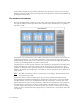
Overview of the VTS web interface VTS is managed through a standard web browser interface. To access the web interface, launch a supported web browser and enter http://ip_address in the address field, where ip_address is the management network interface address of the VTS server. Links on the navigation pane on the left side of the page enable you to navigate through VTS functions.
VTS — Virtual TapeServer, which refers to the Virtual TapeServer engine and provides the core of VTS functionality. SecureVTS If SecureVTS is enabled, this section displays its status. Free Space Optional section that is shown by default.
If VTS is not running, this page displays the following message: “TapeServer is not running!” To start VTS, click Supervisor Functions on the navigation pane and then click Start TapeServer (under Processes). You must have the Stop and Start TapeServer access right to start VTS. The table lists the host devices, pools, and virtual tapes configured on the VTS server. (This information is not listed if VTS is not running.
cartridge maintenance from the window menu, the Virtual Media - Cartridge Maintenance page is displayed: Each Virtual Media page provides an area below the page title devoted to messages generated by VTS as a result of actions you perform on the pages. These messages generally confirm an operation or report an error. Various action buttons are available when you select an option on a page. They are automatically highlighted for use when appropriate.
System Overview page When you click View Configurations on the navigation pane, the following page is displayed. The View/Manage Configuration access right is required to view this page. This page lists the virtual-to-physical mappings for the VTS system. It also lists the virtual, logical, and physical tapes that are available to be mapped.
Manage Tape Connections page This page enables you to manage VTDs. Click Manage Connections on the navigation pane to display this page. The View/Manage Configuration access right is required to view this page.
Supervisory Functions page Click Supervisor Functions on the navigation pane to display this page. The options displayed on this page are based on your access rights; at a minimum, the Supervisory Functions access right is required. Clicking a link on the Supervisory Functions page enables you to perform administrative operations, such as applying updates, editing the configuration file, rebooting the system, downloading files, starting and stopping processes, and examining log files.
Access Control page When you click Access Control on the navigation pane, the Access Control page is displayed. The System Access Controls or User Access Controls access right is required to view this page. If you have the System Access Controls right, this page enables you to grant or limit access to specific VTS functions by managing users and groups. Otherwise, this page enables you to change your password.
Factory Setup page If the Factory Setup option is available, you can click it to display the Factory Setup page: This page enables you to configure VTS and perform administrative functions, such as adding virtual tapes or backing up files. You must have authorized credentials to access this page.
12 | Introduction
Overview of Tasks Initial configuration of the Virtual TapeServer (VTS) should be complete. To complete configuration, perform these tasks, which are described in this guide. To configure VTS 1. Back up the database and configuration files as described in Backing Up the VTS Server on page 15. 2. If necessary, update the VTS software as described in Upgrading, updating, and downgrading VTS on page 117. 3.
• Import and export virtual tapes as described in Exporting and importing virtual tapes or pools on page 63. • View file system (vault) status from the System Status page. • Monitor backups and restores from the Virtual Media page.
Backing Up the VTS Server It is recommended that you back up the VTS server before and after any major operation, such as an upgrade. This section describes how to create a system restore image, to save • All databases • root and bill home directories • Some contents of the /etc and /usr/local/tape/etc directories To create a system restore image 1. Make sure VTS is not in use and that no virtual tapes are mounted. 2. Back up the VTS server, as follows: a.
b. Click Create VTS system restore image. The Creating System Restore Image page is displayed. c. When prompted, choose to save the .tgz file. 3. If SecureVTS is enabled, back up the most current backup of the key database by completing these steps: a. Log in to the VTS server as root. b. Use the su command to change to the bill user: su - bill c.
Modifying Virtual Tape Drives You may need to modify one or more virtual tape drives (VTDs), particularly those that were preconfigured on VTS. You may need to rename VTDs according to your chosen naming convention. This section describes how to modify VTD properties. Note If you delete the VTD, you must restart the TapeServer service. The following table describes the properties that you must set when defining the VTD.
The following procedure describes how to modify a VTD using the Manage Connections page. You can also modify VTDs using the links provided on the page that is displayed when you click Advanced at the bottom of the Manage Connections page. See Advanced Options for Tape Connections on page 159 for more information. Requires the View/Manage Configuration access right To modify the properties of a VTD 1. Click Manage Connections on the navigation pane. 2. Log in.
7. Select the media format from the Tape Type drop-down list. This property defines the type of tape that the VTD emulates. Note Do not select RAID; this option is provided for physical tapes only. 8. From the Bus drop-down list, select the bus ID to which the host server is connected. To determine the bus ID, you must find the PCI slot number on the back of the VTS server module where the SCSI or Fibre Channel cable connects from the card to the target. Labels indicate the bus number for each port. 9.
• For NonStop Integrity (NS) and BladeSystem servers Up to four tape devices are supported per port, therefore you can assign values 0–3 to the LUN. 0 is typically assigned to the LUN for the first tape device, 1 is typically assigned for the second tape device, 2 for the third, and 3 for the fourth. • UNIX servers In general, set the LUN to any value between 0 and 7. Begin with 0 and increment the LUN for each additional VTD that is added on a bus.
Configuring Access Control If you have system administrator privileges, you can configure access control to grant or limit access to specific VTS functions. Each login ID belongs to a group and each group has a unique set of privileges. Note VTS provides a user that has administrator privileges. You can log in as admin if no other administrative user is created on the system. The default password for this user is virtual.
3. Under Defaults and Undo, click the Restore CLOSED Defaults button, which restores all default users, groups, and rights. 4. Click OK on the pop-up dialog box to confirm that you want to restore closed defaults. Below are closed system defaults: • • Users — The following users are defined.
Rights Administration Group Upload VPD X VTS/Linux Configuration Backup X VTS/Linux Configuration Restore Supervisor Group X X View log files X View/Manage Configuration X Virtual Tape Operations Operations Group X X X X Scan and Cleanup Control Panel X X Virtual Tape Cartridge Maintenance X X Delete Cartridges X X Virtual Tape Import and Export X X Virtual Tape Instant DR X X Virtual Tape Mounts and Locks X X Virtual Tape Pool Maintenance X X Erase Cartridges X
Managing users You can add users to VTS or modify settings of an existing user. The following sections describe how to create, modify, and delete users. Note In the following procedures, if the Users and Groups and Rights sections of the Access Control page are not available, you must enable a closed system. These sections are not displayed if the system is configured as open access. Creating a user Requires the System Access Controls access right To create a user 1.
3. Click + to expand Users and Groups. 4. Click ADD. The name and password fields are displayed. 5. Type a username in the name field. Usernames cannot contain spaces and cannot duplicate existing usernames, group names, or reserved names. Also, they must be alphanumeric, though they can include an _ (underscore) character. 6. Type a password in the password field.
7. Click APPLY. The user is added and additional buttons are displayed. 8. To assign the user to a group, click CHANGE GROUP. The Group drop-down list is displayed. Note The user cannot perform functions until you assign the user to a group. 9. Select a group from the drop-down list and click APPLY.
Changing any user’s password It is highly recommended that you change the passwords of the default users. Requires the System Access Controls access right to change any user’s password To change a user’s password 1. Click Access Control on the navigation pane. 2. When prompted, log in. After logging in, the Access Control page is displayed.
3. Click + to expand Users and Groups. 4. Select the user from the Users drop-down list. 5. Click SET PASSWORD. The Password field is displayed. 6. Type a new password in the field. 7. Click APPLY.
Changing your password Requires the User Access Controls access right to change your password only To change your own password 1. Click Access Control on the navigation pane. 2. When prompted, log in. After logging in, the User Access Control page is displayed. 3. Type your current password in the Old password field. 4. Type a new password in the New Password field. 5. Type the new password again in the New Password (again) field. 6. Click APPLY.
Assigning a user to a group Requires the System Access Controls access right To assign a user to a group 1. Click Access Control on the navigation pane. 2. When prompted, log in. After logging in, the Access Control page is displayed. 3. Click + to expand Users and Groups.
4. Select the user from the Users drop-down list. The SET PASSWORD and CHANGE GROUP buttons are displayed. 5. To assign the user to a group, click CHANGE GROUP. 6. Select a group from the drop-down list and click APPLY. Deleting a user Requires the System Access Controls access right To delete a user 1. Click Access Control on the navigation pane. 2. When prompted, log in. After logging in, the Access Control page is displayed.
3. Click + to expand Users and Groups. 4. Select the user from the Users drop-down list. 5. Click REMOVE. 6. When prompted, click OK to confirm that you want to remove the selected user.
Configuring groups Groups define the access rights that are assigned to users. Three groups are provided: Administration, Operations, and Supervisor. For a list of the default rights assigned to these groups, see page 22. You can modify the access rights that are assigned to these groups. You can also save your changes as a set of custom defaults, which can be restored later if necessary.
3. Click + to expand Rights. 4. To modify access rights assigned to the Administration group, select the checkbox next to each access right in the Administration column. Note The rights are organized in categories. If you grant access to a category, all rights in the subcategories are granted by default, though you can remove individual rights in the subcategories.
Right User Access Controls Description Enables the user to change his or her password only within Access Control Block and Unblock TapeServer Displays the Block & Unblock TapeServer link on Supervisory Functions page, which enables the user to block and unblock VTS functions Database Download Enables the user to download the database from the Supervisory Functions page Database Upload Enables the user to upload a database from the Supervisory Functions page Edit VTS Configuration File Enables the u
Right Description Scan and Cleanup Control Panel Grants access to the Virtual Media - Scan/ Cleanup page Virtual Tape Cartridge Maintenance Grants access to the Virtual Media - Cartridge Maintenance page Delete Cartridges Enables the user to delete virtual tapes from the Virtual Media - Operation and Virtual Media - Cartridge Maintenance pages Virtual Tape Import and Export Grants access to the Virtual Media - Import/ Export page Virtual Tape Instant DR Grants access to the Virtual Media - Insta
5. To modify access rights assigned to the Operations group, select the checkbox next to each access right in the Operations column. See step 4 for a description of each right. 6. To modify access rights assigned to the Supervisor group, select the checkbox next to each access right in the Supervisor column. See step 4 for a description of each right. 7. Click APPLY above the table to save your changes.
2. When prompted, click OK to confirm that you want to save the settings as the custom defaults. The Restore CUSTOM Defaults button becomes available in the Defaults and Undo section of the page. To restore the custom default settings Click the Restore CUSTOM Defaults button to restore the custom configuration and discard changes made since the custom defaults were last saved.
Configuring EMS Communication To automate the process of mounting and dismounting virtual tapes, you must configure the Event Management System (EMS) on Virtual TapeServer (VTS). The EMS service starts the EMS distributor on the NonStop server by issuing a Tandem Advanced Command Language (TACL) command. The distributor notifies the VTS EMS service when an EMS message is posted on the NonStop server.
c. Click Show General Settings. The following fields are displayed: d. To enable EMS, select the Enable EMS checkbox. e. f. To configure VTS to generate EMS messages for notifications, set the following: • To enable VTS to send notification messages back to the NonStop host from EMS messages, select Enable Host Notifications. • If you enabled notifications, set the notification level from the Notification Level drop-down list.
5. Click Save EMS Configuration to save the settings. 6. Define the EMS hosts that identify the NonStop servers for which a Telnet session will be established. a. Click the New EMS Host button. The following fields are displayed: b. Specify a name for the host in the Host ID field. This is used for display purposes only. c. In the Host Name or IP field, specify a hostname or IP address of the NonStop server for which a Telnet session will be established.
d. To define the service settings, set the following: e. • In the Service Prompt field, specify the service selection prompt to which the EMS login process responds and begins. Specify any search pattern as a Perl regular expression, and the special %username% and %password% values may be used in responses to equate to those values (see step 8 on page 44 for values). Example: /^Enter Choice>\s*$/i • In the Service Answer field, specify the service response.
g. In the Notify Wait Timeout field, specify the number of seconds to allow the host to process commands before VTS expects to prompt for another command. Typically, this should be 2-3 seconds but it causes no harm to allow more time for the host. h. In the Notify Logout Timeout field, specify the number of seconds to wait after issuing the LOGOUT command and before closing the socket connection. i.
8. Set the username and password for each EMS host: a. Click Supervisor Functions on the navigation pane. b. Click Manage Passwords. The following page is displayed: c. From the drop-down list, select the EMS host. Note If the EMS hostnames are not in the list, EMS may not be enabled. d. In the Username field, type a username for that host. e. In the New Password field, type a password for the user. f. Retype the password in the New Password (again) field. g. Click Update. h.
Configuring Web Interface Preferences This chapter describes how to configure web interface preferences by setting parameters in the configuration file and how to set the refresh rate of the System Status page. Enabling features on the web interface You can set a number of parameters in the VTS configuration file to specify the following: • Whether to display the buttons and features on the Virtual Media - Operation page. • Whether and how often to display status messages at the top of the page.
Parameter Description Values opwin_Delete Displays the Delete button on the Virtual Media - Operation page. YES or NO Default value: YES opwin_ImportExport Displays the Import/Export button on the Virtual Media - Operation page. YES or NO Default value: YES opwin_Migrate Displays the Migrate button on the Virtual Media - Operation page. Note that the hsm_enable parameter must also be set to YES to display the button.
Parameter Description Values notifications_interval Specifies how often to check for notifications, in seconds. Integer Default value: 60 lowspace_notify Enables notification on low vault space. YES or NO Default value: YES lowspace_notify_keep Specifies whether to continue to display the low vault space notification until it is no longer valid.
status_ChangeRate="YES" status_StopStart="YES" 4. Click the SAVE button. Setting the refresh rate The System Status page is refreshed every 15 seconds by default. Requires the Change Refresh Rate access right To configure the refresh rate 1. Click System Status on the navigation pane. 2. Click the Change Rate button at the bottom of the page. The following page is displayed: 3. Click one of the buttons or specify a value (in seconds) in the field and click the Set Refresh Rate button. 4.
Managing Pools and Virtual Tapes Virtual TapeServer (VTS) organizes data in vaults, which in turn contain pools. The pools contain virtual tapes. Vaults are defined for you based on your input by the onsite Integration Engineer. This chapter describes how to create and modify pools and virtual tapes. It also describes how to erase, delete, import, and export virtual tapes. Managing pools This section describes how to create and modify pools on the Pool Maintenance page.
3. Select a vault from the VAULT drop-down list. 4. Enter a name for the NEW POOL field. Specify a name that is up to 255 alphanumeric characters in length. Note The pool name must be unique across all vaults on the VTS server. 5. To set a size limit on the pool, deselect the Cartridge Size unlimited checkbox and enter a size (1 - 1023) in the field. Select Megabytes, Gigabytes, or Terabytes from the drop-down list. This sets a maximum size for the virtual tapes in the pool.
9. If the SecureVTS feature is enabled, you can select the Encrypted checkbox to encrypt all cartridges that are added to the pool. See Using SecureVTS on page 69 for more information about this feature. 10. Click the CREATE button. You can click the pool drop-down list to confirm that the pool was created. When you return to the Virtual Media - Operation page, the new pool is listed and a red dot is displayed to the left of its name.
Gigabytes, or Terabytes from the drop-down list. This sets a maximum size for the virtual tapes in the pool. Note If you select the Cartridge Size unlimited checkbox, VTS can create virtual tapes up to 2TB. However, virtual tape sizes may still be limited due to file-system constraints. 7. If you want to set a limit to how long the virtual tapes in the pool are stored, deselect the Retention unlimited checkbox and specify a value in the field.
Deleting a pool When you delete a pool, all virtual tapes in the pool are also deleted. Requires the Virtual Tape Pool Maintenance, Vault Access, and Access to all Vaults access rights; if the pool contains encrypted tapes, the user must also be a member of the Administration group To delete a pool 1. Click Virtual Media on the navigation pane. 2. Select pool maintenance from the window drop-down list at the top of the Virtual Media - Operation page. The Virtual Media - Pool Maintenance page is displayed.
Managing virtual tapes You must create a virtual tape before the host server can mount and write data to it. When you create a virtual tape, a file is created on the VTS server’s disk.
Creating a single virtual tape Requires the Virtual Tape Cartridge Maintenance, Vault Access, and Access to all Vaults access rights To create a virtual tape within a pool 1. Click Virtual Media on the navigation pane. 2. Select cartridge maintenance from the window drop-down list at the top of the Virtual Media - Operation page. The Virtual Media - Cartridge Maintenance page is displayed. 3. Select a pool from the Pool drop-down list. This is the pool in which the virtual tape will be created. 4.
Creating multiple virtual tapes Requires the Virtual Tape Cartridge Maintenance, Vault Access, and Access to all Vaults access rights To create multiple virtual tapes at once 1. Click Virtual Media on the navigation pane. 2. Select cartridge maintenance from the window drop-down list at the top of the Virtual Media - Operation page. The Virtual Media - Cartridge Maintenance page is displayed. 3. Select a pool from the Pool drop-down list. This is the pool in which the virtual tapes will be created. 4.
tape creation error is encountered. This may result in a partial, non-contiguous set of tapes. However, a message is displayed indicating how many tapes were created. 8. Click CREATE. Note The names applied to virtual tapes are not tape labels. They are equivalent to the stick-on labels applied to physical tapes. When you return to the primary operation screen, + is displayed next to the pool indicating that it now contains virtual tapes. Mounting a virtual tape You can manually mount a virtual tape.
4. Click Mount. The following dialog box is displayed. Note If the Mount button is not displayed, see Enabling features on the web interface on page 45 for information about displaying this button. Also, if you cannot click the Mount button, maximize your browser; this should display an arrow cursor and enable you to click the button. See the Release Notes for more information. 5. Click OK to mount the virtual tape for read and write operations. Click Cancel for read operations only.
Erasing and deleting virtual tapes You can erase the contents of a virtual tape or remove the tape altogether. To perform these operations, you must unmount the virtual tape first, if it is mounted. The following sections describe how to manually erase and delete a single tape or multiple tapes. You can also automate these operations from the NonStop server using the VTSPolicy command if Event Management Service communication is configured. (See Configuring EMS Communication on page 39.
2. Select a virtual tape in the cartridge column. You may need to expand a pool to see the list of virtual tapes. 3. Click Erase to erase the contents or click Delete to delete the entire tape. Note If the Erase or Delete button is not displayed, see Enabling features on the web interface on page 45 for information about displaying these buttons. 4. When prompted, click OK to confirm the operation. To erase or delete a virtual tape from the Cartridge Maintenance page 1.
Multiple virtual tapes You can erase or delete multiple virtual tapes from the Virtual Media - Cartridge Maintenance page only.
7. Click ERASE or DELETE. 8. When prompted, click OK to confirm the operation. Automation using VTSPolicy commands The VTSPolicy command enables you to automatically erase or delete specific virtual tapes directly from a NonStop server. You can initiate these operations by configuring the NonStop server to send an EMS message to VTS. You can configure the NonStop server by defining a file utility program (FUP) call or by creating a Tandem Advanced Command Language (TACL) macro.
#SET evt_num number Assigns a number to the event. #SET action -1 Refers to the way the message is displayed in an EMS viewer, such as ViewPoint. In this case, it is inverse text until acknowledged. #SET emphasis -1 Refers to the way the message is displayed in an EMS viewer, such as ViewPoint. In this case, it is normal text. #SET evt_text VTSPolicy Erase|Delete - virt_tape... [s=hostname] Specifies the message to be sent to the EMS collector.
stored as a virtual tape. If you export a pool, you can only import the tape(s) back into VTS. Also, when exporting a pool, only those virtual tapes that contain data are exported. Requires the Virtual Tape Import and Export, Vault Access, and Access to all Vaults access rights To export a virtual tape or pool 1. Click Virtual Media on the navigation pane. The Virtual Media - Operation page is displayed. 2. Select a pool in the pool column.
3. Click Import/Export. Or, if SecureVTS is enabled and the tape is encrypted, click Import/Decrypt&Export. The Virtual Media - Import/Export page is displayed. If one or more physical tape drives are connected to VTS, they are detected automatically. (If a physical tape drive is not listed, such as if it was connected after VTS was booted, you may need to rescan the SCSI controllers. See Common issues on page 123 for more information.
Requires the Virtual Tape Import and Export, Vault Access, and Access to all Vaults access rights To import a physical tape Note that you must select a virtual tape to which the data on the physical tape is imported. If data exists on the selected virtual tape, it is overwritten when the data is imported. 1. Click Virtual Media on the navigation pane. The Virtual Media - Operation page is displayed. 2. Select a pool in the pool column. Or, expand a pool and select a virtual tape in the cartridge column.
3. Click Import/Export. Or, if SecureVTS is enabled and the tape is encrypted, click Import/Decrypt&Export. The Virtual Media - Import/Export page is displayed. If one or more physical tape drives are connected to VTS, they are detected automatically. Note If the Import/Export button is not displayed, see Enabling features on the web interface on page 45 for information about displaying this button. 4. Click IMPORT. 5.
Verifying virtual tapes are available from the host server To verify that a tape is available on VTS, check the virtual tape size on the Virtual Media Operation page. The size(MB) column indicates whether a tape is unlabeled (empty) and indicates the data capacity that is used after a backup runs. (If a labeled tape is erased, the value in this column returns to 0.) If you click the link, a pop-up dialog box is displayed listing tape data. Remember that the size is compressed.
Using SecureVTS SecureVTS is an optional Virtual TapeServer (VTS) software module that enables VTS to encrypt data that is stored on virtual tape. SecureVTS encrypts data when storing it on a virtual tape. Here is how SecureVTS affects tape operations: • When an encrypted tape is mounted, the data that is written to the tape is encrypted. You can also instruct SecureVTS to encrypt data that is already stored on a virtual tape if the tape is not encrypted.
Encryption and decryption during virtual tape operations A virtual tape can be encrypted in several ways: • It can be encrypted when it is created. • It can be manually encrypted after it is created. • It can be automatically encrypted when it is added to a pool that is designated as encrypted. • It can be encrypted if the pool in which it resides is designated as encrypted. Similarly, a virtual tape can be decrypted manually or when its pool is decrypted.
Multi-server considerations Keep the following in mind when configuring and using SecureVTS in an environment with multiple VTS servers, such as if GFS, AutoCopy, or Instant DR is configured: • SecureVTS configuration When configuring key servers and backup hosts for SecureVTS, it is highly recommended that you configure only one key generator for the environment. You must also configure at least one other server in the environment that can serve as the backup host for the key database.
If three VTS servers — A, B, and C — are installed in your environment, you must perform these tasks to fully enable and configure SecureVTS: 1. Determine which server will be responsible for generating keys. For this example, server A will be the “key generator”. 2. Add server A as a key generator on servers B and C. 3. On servers B and C, remove the localhost key server. (The localhost entry is configured as a key generator.) 4.
Prerequisites for configuration Before you begin, you may want to gather the following information to expedite the configuration process: • Username and password of a VTS user account that belongs to the Administration group. • If multiple VTS servers are installed, gather the following: • Hostname or IP address, username, and password of the VTS server that will be configured as the key generator, which will generate keys when virtual tapes and pools need to be encrypted and decrypted.
3. Click ADD NEW SERVER in the KEY SERVERS section of the page. The following is displayed: 4. In the Host/IP Address field, type the hostname or IP address of a VTS server in your environment that you would like to designate as a key server. 5. In the Port Number field, type the port number of the key server, which is 9090 by default. 6. Select the Key Generator checkbox to enable the key server to generate keys.
When you add a backup host, VTS immediately sends a copy of the local key database to the host. This tests the connection to the host and validates the host parameters that you specified. If a copy of the key database exists on the target host, it is overwritten. Note You cannot modify a key database backup host after it is added. To change the settings of a backup host, you must delete it and then add it again, specifying the correct parameters.
Encrypting and decrypting virtual tapes After SecureVTS is enabled and configured, you can encrypt virtual tapes. You can encrypt virtual tapes individually or you can encrypt a pool, which instructs VTS to automatically encrypt virtual tapes when they are added to the pool. • If you encrypt a pool, all virtual tapes in the pool are encrypted when they are created. • If virtual tapes exist in a pool before the pool is encrypted, you can choose whether to encrypt the existing virtual tapes.
5. Select the Encrypted checkbox. (This option is not available if you have not enabled SecureVTS, if you have not logged in, or if you select a vault.) 6. When prompted, click OK to confirm that you want to encrypt all virtual tapes that currently reside in the pool plus tapes that are added to the pool. Or, click Cancel to encrypt only virtual tapes that are added to the pool. 7. Click APPLY on the Virtual Media - Pool Maintenance page.
Decrypting a pool When you decrypt a pool, you are prompted to decrypt all virtual tapes in the pool. After decrypting the pool, virtual tapes are no longer encrypted when they are added to the pool. Requires Administration group membership To decrypt all virtual tapes in a pool 1. Click Virtual Media on the navigation pane. 2. If prompted, log in using an account that is a member of the Administration group. Click the Log In button at the top of the page and enter a username and password. 3.
Managing the SecureVTS configuration You may need to remove a server from the SecureVTS configuration, or you may need to manually backup or restore a key database. The following sections describe how to perform these tasks. Managing licensing After you initially enable licensing, you can update the license key or remove it. Obtain the SecureVTS license key from your Sales representative. To update the license key 1.
3. Click Manage System Licenses. 4. Click REMOVE next to the Secure VTS Key. 5. On the pop-up dialog, click OK to confirm that you want to remove the key. Restoring a key database You can restore a key database, such as if you are reinstalling a server. You can restore a key database from one of the backup hosts listed on the SecureVTS page, which overwrites the localhost’s key database with the most recent backup on the selected backup host.
3. Click the Restore from Disaster Recovery Site button in the KEY DATABASE BACKUP/RESTORE HOSTS section of the page. The following is displayed: 4. In the Host/IP Address field, type the hostname or IP address of the remote server from which VTS will retrieve the key database. 5. In the Username field, type the username of a user account that can access the SCP program on the specified server. 6. Type the password of the user account in the Password field. 7.
5. Re-add the key server(s) as described in Adding a key server on page 73. This ensures that the key servers are created with the current server’s credentials. 6. Re-add the key database backup host(s) as described in Adding a key database backup host on page 74. Backing up a key database Each key server automatically backs up its key database when a new key is generated. However, you can manually back up a key database. Requires Administration group membership To manually backup a key database 1.
Deleting a key database backup host You can remove a backup host so that the key server no longer backs up its database to that server. Note You cannot modify a key database backup host. To change the settings of a backup host, you must delete it and then add it again, specifying the correct parameters. Requires Administration group membership To delete a backup host 1. Click SecureVTS Setup on the navigation pane. 2. If necessary, log in using an account that is a member of the Administration group.
84 | Using SecureVTS
Using Scan/Cleanup Scan/Cleanup is a Virtual TapeServer (VTS) feature that is designed to help you maintain VTS. It scans pools and virtual tapes to identify virtual tapes that are past their retention period. Scan/Cleanup can erase old virtual tapes to recover disk space. You can also schedule virtual tape erasures when the overall disk space falls below a specified threshold. Scan/ Cleanup can be used to erase tapes after migration.
Enabling and configuring Scan/Cleanup You must modify the VTS configuration file to enable Scan/Cleanup and configure some of the business rules. Requires the Edit VTS Configuration File access right To configure Scan/Cleanup Note A default configuration file is defined for each VTS server. To override the default settings, you must define settings as described below. 1. Click Supervisor Functions on the navigation pane. 2. Click Edit VTS Configuration File. 3.
Parameter Description Values cleanup_scan_at Specifies when the automated scan and erasure should run. A typical setting would be 04:30, which indicates to run at 4:30AM. To avoid scheduling problems, set this parameter greater than 00:04 and less than 23:51. Specify 00:00 to disable this feature. Scheduling this once or twice a day should be frequent enough to manage disk space utilization.
Parameter Description Values cleanup_minimum_size_ GB Define which files to ignore based on size by using either cleanup_minimum_size_MB or cleanup_minimum_size_GB, but not both. The specified value is used to set the minimum file size to erase. Some installations have many small virtual tapes and do not require that they be erased. For larger tape sizes, use the cleanup_minimum_size_GB parameter; for smaller sizes, use the cleanup_minimum_size_MB parameter.
Parameter Description Values cleanup_show_size_ column Shows or hides the Size column in the Status Table. YES or NO Default value: NO meta_control_panel Shows or hides the Meta Data Control Panel, which enables you to read and write metadata on the virtual tape. Set this parameter only if diagnosing problems or instructed to do so by Support.
Overview of the Scan/Cleanup page After you enable Scan/Cleanup, you can display the web interface for this feature by clicking Virtual Media on the navigation pane. Then, select scan/cleanup from the window dropdown list. The Scan/Cleanup page is displayed. Click the Show/Hide ‘No’ button to display the cartridges: Here is a description of the status tables, fields, and buttons on this page: Status table This table lists all virtual tapes on the system and their Scan/Cleanup status.
Size Displays the size of the virtual tape (in bytes). This reflects the size of the tape data; it excludes the size of the metadata (up to 27MB). Erase Indicates whether the virtual tape is selected for erasure or not. This column also provides an explanation of the business rule that is controlling the erasure status. In the following example, virtual tape X00001 was erased on 13Feb05 15:43, last written on 17Feb05 14:49, will be retained for two weeks, and has never been migrated.
Also, if the meta_control_panel parameter is set to YES, the Meta Data Control Panel is displayed at the bottom of the page. This control panel enables you to read and write metadata. Metadata is stored with the virtual tape but is not part of the data itself.
Using Instant DR Instant DR is an advanced software module that enables you to create and maintain identical copies of backup data on Virtual TapeServer (VTS) disk storage at one or more locations. In the event of a disaster, remote recovery operations can begin immediately using the backup data copy on a remote VTS server. Instant DR is designed to transmit data from one site to another over a wide area network (WAN). Virtual tapes are transmitted from one vault to another.
that the operation failed. See Using SecureVTS on page 69 for more information about the SecureVTS feature. See SecureVTS and failed tape operations on page 127 for an explanation of the possible failures. In general, Instant DR should be used if files do not change much from day to day. Data is transmitted in batches, one or more times per day, and only data differences are sent. Bandwidth is consumed when the data transmission is scheduled according to policy, usually during off-peak hours.
Requires the Virtual Tape Instant DR access right To create an Instant DR jobset 1. Click Virtual Media on the navigation pane. 2. Select instant dr from the window drop-down list at the top of the page. 3. Click NEW in the Select Backup Set section of the page. 4. In the Enter new job name field, type the name of the jobset. 5. Click SUBMIT to continue. The following page is displayed: 6. In the Backup target system field, type the name or IP address of the system to receive the backup.
7. In the Directory field, type the full path to the target vault (in UNIX notation). The path must begin with the vault where the backup will be made. The remainder of the string is specific to your environment. 8. Select the Use Secure Transfer checkbox if SSH is configured on the VTS systems and you want to encrypt the information being transmitted. This transfer method is not necessary if the connection between the VTS systems is secure or in a trusted environment.
tapes than the ones you are working with. The asterisk is the only wildcard character accepted and can be used only in the cartridge field. It can appear anywhere in the name (before, after, or in the middle). It can also appear by itself to designate all virtual tapes in the pool. If the All Files checkbox is not selected, VTS finds the virtual tape identified with a wildcard that has most recently been modified.
indicates finished. The virtual tape is available on the remote VTS server until it is needed or until the process runs again and updates it. To display complete job log information on the process, click §. Automating Instant DR backups from the NonStop server You can initiate an Instant DR jobset by configuring the NonStop server to send an EMS message to VTS. This automates the Instant DR process. VTS parses the message and executes the specified Instant DR jobset.
#SET emphasis -1 Refers to the way the message is displayed in an EMS viewer, such as ViewPoint. In this case, it is normal text. #SET evt_text VTSPolicy IDR idrjobname Specifies the message to be sent to the EMS collector. Replace idrjobname with the name of the Instant DR job in VTS. Add these lines to the end of an existing obey script or schedule it from Batchcom.
3. Click Manage System Licenses. The following page is displayed: 4. Select the Update checkbox for the IDR Key. 5. In the IDR Key field, type the license key. 6. Click SUBMIT. 7. On the pop-up dialog, click OK to confirm that you want to add the key. To remove a license key 1. If necessary, log in to the VTS web interface using an account that is a member of the Administration group. Click the Log In button at the top of the page and enter a username and password. 2.
Using AutoCopy AutoCopy is an optional Virtual TapeServer (VTS) software module that enables you to copy a virtual tape from one VTS system to another when the virtual tape is mounted, modified, and dismounted by the NonStop host.
Note A default configuration file is defined for each VTS server. To override the default settings, you must define settings as described below. Requires the Edit VTS Configuration File access right To modify the VTS configuration file to configure AutoCopy 1. Click Supervisor Functions on the navigation pane. 2. Click Edit VTS Configuration File. 3. Add the following parameters at the bottom of the file that is displayed: Parameter Description Values autocopy_enable Enables AutoCopy.
Parameter Description Values autocopy_target_ ANYPOOL Specifies the target of the copy operation for all pools set by autocopy_pools. Specify this parameter if you do not set the autocopy_target_poolname parameter for each pool in autocopy_pools. See details about how to set this parameter in the description of autocopy_target_ poolname. VTS system name or, vault on a VTS system, such as / VAULT00/ server1 or, pool on a target system, such as server1:pool1 4. Click SAVE.
104 | Using AutoCopy
Migrating Data to Physical Tape Migration allows for better use of the disk space on the storage array. Migration relies on the use of a backup management application. To automate migration, you can configure the VTSPolicy command in conjunction with the Event Management Service (EMS) on VTS. You can manually initiate migration by clicking the Migrate button on the Virtual Media Operation page. A backup management application client must be installed on the VTS server to enable manual migration.
Manually migrating virtual tapes You can migrate a pool, which migrates all virtual tapes in the pool, or a single virtual tape. The virtual tape or pool is migrated according to the hsm_ parameters in the VTS configuration file. Requires the HSM Migration access right To migrate data 1. Click Virtual Media on the navigation pane. The Virtual Media - Operation page is displayed: 2. Select a pool to migrate by clicking on the name of a pool in the pool column.
If the return code indicates a failure, VTS does not mark the virtual tape as migrated and notes this in the log file. If the NonStop server requests a virtual tape that was migrated, VTS checks the size of the requested virtual tape. If the size is 0, the virtual tape was erased and VTS attempts to retrieve the data and recreate the virtual tape from physical tape.
notify Enables VTS to log migrated virtual tapes to $logdir/notifications.log. Set this keyword to YES or NO. This keyword is not required and defaults to NO. unlock Unlocks all specified virtual tapes before completing the migration. Set this keyword to YES or NO. This keyword is not required and defaults to YES.
The VTSPolicy command for Syncsort Backup Express Here is the syntax of the VTSPolicy command for use with Backup Express. Note that all parameters specified for the command are case-sensitive. VTSPolicy BEX 'backup_type /VAULTxx/pool/cartridge [keyword=value ...]' where backup_type. Specifies the type of backup. You can specify one of the following values: backup_base or backup_difr. /VAULTxx/pool/cartridge Specifies the pool and cartridge on which to operate.
For example, to migrate the virtual tape named CART01 on the VTS1 server and erase the selected files from VTS, issue the following command: VTSPolicy NBP '/VAULT01/POOLA/CART01 s=VTS1 erase=YES' The VTSPolicy command for CommVault Galaxy Here is the syntax of the VTSPolicy command for use with CommVault Galaxy. Note that all parameters specified for the command are case-sensitive.
Specify how the message will be displayed in an EMS viewer, such as ViewPoint. In this example, inverse text is used until the event is acknowledged but the event is listed in normal text: #SET action -1 #SET emphasis -1 Issue the VTSPolicy command; see Automating migration using VTSPolicy on page 106 for an explanation of the parameters.
Modifying the user account During configuration, a user account is configured that enables VTS to log in to the backup management application. You can change the username or password, if necessary. Note This procedure is required for Backup Express and NetBackup only. To modify the backup management application account 1. Click Supervisor Functions on the navigation pane. 2. Click Manage Passwords. The following page is displayed: 3. From the drop-down list, select hsm. 4.
Performing Administrative Tasks This chapter describes several tasks that are performed from time-to-time as needed. Maintaining mounts and locks If EMS was enabled, the process of mounting virtual tapes is automated; the NonStop server can initiate mounts and dismounts. (For details, see Configuring EMS Communication on page 39.) When VTS detects a mount request, it checks to see if the requested virtual tape resides on a RAID array connected to VTS.
any of the cartridges in a pool. Under normal conditions, manual lock maintenance is not necessary; these locks are created and deleted by the VTS processes. Removing a lock here should only be done if a VTS process terminated abnormally. To remove a lock, select the pool or virtual tape and click REMOVE LOCK. Managing licensing After VTD licensing is initially enabled, you can update the license key (to add to or subtract from the number of licensed VTDs, and to add or remove compression) or remove it.
5. In the VTD Key field, type the license key. 6. Click SUBMIT. 7. On the pop-up dialog, click OK to confirm that you want to add the key. 8. Restart the TapeServer service. Click Supervisor Functions on the navigation pane. On the Supervisory Functions page, click Stop TapeServer and then click Start TapeServer. If the license key enables fewer VTDs than the previous license key, the following error is displayed on the Virtual Media - Operation page: Also, you cannot mount a drive or virtual tape.
3. Start tape services on the NonStop server using the SCF START $VTAPE command, where VTAPE is the name of the tape device. Here is an example of the output of this command: SCF - T9082H01 - (04DEC06) (15NOV06) - 10/02/2008 11:58:32 System \DEV5 (C) 1986 Tandem (C) 2006 Hewlett Packard Development Company, L.P.
Upgrading, updating, and downgrading VTS This section provides procedures for upgrading, updating, and downgrading the VTS installation. Upgrading the VTS server To upgrade to 6.04.x, you must first upgrade to 6.04.01. The instructions for upgrading to 6.04.01 can be found at http://docs.hp.com/; search for “Virtual Tape Server 6.04 Operations and Administration Guide”. Refer to the Upgrading VTS appendix and be sure to review checklist of items to consider before beginning the upgrade process.
11. Select From File on the VTS Revision Update page. 12. In the Location of VTS Revision Update File field, type the full path to the UPG file. 13. Click UPGRADE. 14. Click OK to continue. 15. Confirm that the following message is displayed: Successfully delivered upgrade_processing.php. 16. Click REBOOT to complete the update. Updating the VTS server If you need to install an interim release (IR) or patch, complete the following steps.
Downgrading the VTS server Complete the following steps if you want to downgrade the server (to a previously installed version of 6.04). The following occurs when you downgrade the server: • Backup of /usr/local/tape/ is restored • System restore image is restored • VTS server is downgraded Note Operating system RPMs that were installed during an upgrade are not reverted. If desired, you must manually uninstall these RPMs.
/var/log Contains system log files /usr/local/tape/log Contains VTS log files /usr/local/tape/trace Contains trace logs generated by some programs /var/spool/mail Contains user mail folders. /var/spool/mqueue Contains outbound mail /var/spool/clientmqueue Contains outbound mail not yet processed by the host’s MTA. It is recommended that you monitor these directories and archive (or purge) old files as needed.
Troubleshooting This chapter provides information to assist you in addressing problems you may encounter while installing and using Virtual TapeServer (VTS).
Virtual Network Computing remote control software VNC software enables you to remotely access the console of a UNIX server. VNC must be configured on the host server before you can use it from a client. You can download VNC from http://www.vnc.com/. HP health monitoring utilities The VTS server provides the following: • HP Systems Insight Manager (HPSIM-Linux-C.05.02.02.00.bin) • HP System Health Application and the HP Insight Management Agents (hpasm-8.0.0173.rhel5.x86_64.
Common issues The following sections provide general information to diagnose hardware components and software features of the VTS system. NonStop server If error 190 occurs on the Subsystem Control Facility (SCF), perform the following: • Check the power on VTS. • Check the SCSI converter. (Blue LED indicates power is on.) • Check the SCSI cable connections for bent or loose pins. • QTOS users must stop the QTOS process before stopping or starting a virtual tape drive from SCF.
A green LED indicates normal operation; amber indicates failure. You can also remove all hard drives and reseat them individually. Be sure to properly shut down VTS before performing this operation. SCSI controllers You can rescan all SCSI controllers to list devices. Be sure to stop the tape drives in SCF on the host server before initiating the scan. Use these commands to rescan the SCSI controllers: cd /usr/local/tape/bin ./rescan-scsi-bus.
Web interface If the web interface stops responding, verify the following: • Access the interface from a different workstation. • Ping the address. • Check the Ethernet cable. • Check Ethernet connectivity and activity LEDs. The Apache web server is responsible for running the VTS web interface. To verify that Apache is running: /etc/init.d/httpd status A message similar to the following should be displayed: httpd (pid 25380 25015 25014 25013 25012 25011) is running...
Event Management System (EMS) Verify the following: • Has the EMS logon expired? • Is there network connectivity between VTS and the NonStop server? • Was the VTS operating system or the EMS template upgraded? • Is VTS up-to-date with the latest product enhancement code? • Is there a typographical error in the VTS configuration file? You can check the EMS log file for the last timestamp of messages.
• Check that the tape is in the drive. • Check the media write-protection. If you cannot access a virtual tape because it is locked, perform the following: • Check MEDIACOM for label in use. • Check other VTS systems for remotely mounted virtual tapes. • Reboot VTS to clear all local file locks. If an autoloading pool did not recycle, verify that Autoloading or Recycle is selected on the Pool Maintenance page.
• Erasing all virtual tapes in a pool on the Cartridge Maintenance page: A message similar to the following is displayed on the web interface: Erased 1 cartridge; Erasure of cartridge SH0002 in pool SHARE failed! • Setting the virtual tape size on the Pool Maintenance page: A message similar to the following is displayed on the web interface: Unable to set size limit on SHARE:SH0001, rc=2.
Each log file is rotated once the log file reaches a size greater than 10KB. When the size limit is reached, the old log is renamed to a new name containing the rotation number (such as debug.log.1) and a new (blank) log begins with the default name. All rotated log files are compressed (using gzip) after the second rotation except for the first log file (most recent). If the file is compressed, .gz is appended to the log file name. This file is renewed each day at 4 a.m.
Log format Each entry in the event log follows the same format, as shown in the following example: 2006-08-28 16:25:18|WARNING|440002|5900-E| 127.0.0.1|Tapeserver01|administrator||Access Control RESTORE OPEN defaults have been restored Messages are up to 255 characters in length; each message field has a character limit. The attributes that have a variable length are automatically compressed to the available space.
Message severity The severity attribute indicates the potential impact of the event or condition that the message reports. Note Though you can change the debug level on the Set Debug Level page, the debug level is reset to Error every time VTS is restarted. The following table lists the severity levels for log messages, starting from the lowest level of impact to the highest. Severity ID Severity Level Description 2 Info A normal operation.
ID Subsystem 53 Virtual tapes 61 Access Control defaults 62 Access Control users 63 Access Control groups 64 Access Control rights 65 Secure password management 71 Erase by list 72 Delete by list 81 Crumb 91 System status Logwatch reports Daily Logwatch reports enable you to view significant events that occurred on the system in the last 24 hours. The reports are generated by parsing events in the Linux log directory (/var/log) and VTS log directory (/usr/local/tape/log).
To enable remote logging 1. Log in to the VTS server as bill. 2. Use the su command to change to the root user: su 3. Edit /etc/syslog.conf and add the following line: kern.* @loghost where loghost is the name of the remote server. kern.* specifies to log all kernel messages. To log other messages, refer to the syslog.conf man page. 4.
• /usr/local/tape/log/ems.lastmount.cmd • /usr/local/tape/log/rescan.txt • /usr/local/tape/log/SecureVTS.log Note Though you can change the log level of these files, the log level is reset to the default every time VTS is rebooted.
Message Text Severity Recommended Action AUTOCOPY FAILED: Request by: $requestor ($retry_number) cannot reach $target/$filename (rc=$rc) Critical No action is required. The task will be retried. AUTOCOPY FAILED: Requested by: $requestor ($retry_number) from $target/$filename(rc=$rc) Critical The autocopy task failed. Correct the problem and resubmit the job.
Message Text Severity Error: Can’t find any files with data to backup for $cart_request. Warning Error: Can’t get lock for $cart_request. Critical Check the Virtual Media - Mounts and Locks page to ensure that the virtual tape exists on the system and that another process has not locked the virtual tape. Error: Can't verify lock for $cart_request.
Message Text Severity Recommended Action Error: TSM command failure for $cart_request. Warning The tsm_version parameter is not configured properly in the VTS configuration file, which is available on the Supervisory Functions page. Error: Unrecognized product specification; $hsm for $cart_request. Critical The hsm_product parameter is incorrect. Repair and resubmit the request. Error: Unrecognized product specification; $hsm for $cart_request. Critical The hsm_product parameter is incorrect.
Message Text Severity Restored $count file(s) Inform Restored $count file(s), rc=$rc Inform vtape_ems.php cancel processing Inform vtape_ems.php processing mount of $tape Inform Warning: hsm_opt_$pool is not defined. Critical The hsm_opt_pool parameter is required but missing from the VTS configuration file, which is available on the Supervisory Functions page.
Adding Vaults on External Storage If an external storage device is connected to Virtual TapeServer (VTS) and you want to configure additional vaults, use the instructions in this appendix to create the vaults. Up to 100 vaults are supported per VTS server. Note If GFS is used in your VTS environment, see Maintaining GFS for VTS on page 147 for instructions to create vaults. To add a vault to VTS 1. If necessary, connect the external storage device to VTS over Fibre Channel.
These are the device names for the SCSI disks that the operating system recognizes on boot. Each line indicates the host number, bus, SCSI ID, LUN, and SCSI type for each device. For example, look at the /dev/sda line, which provides information about the /dev/sda device, the following information is listed: Host number = 12 Bus = 0 SCSI ID= 0 LUN = 1 SCSI type = 0 4. If the disk partition is less than 2TB in size, complete the following steps to configure the disk partition: a.
c. Create a 4TB primary partition at the beginning of the disk: mkpart primary 0 4000G d. Quit parted. quit 6. Format the disk partition by entering the following command: mke2fs -j -L /VAULT01 /dev/sda1 When specifying a vault name, use the following format: VAULTnn, where nn indicates a number. Repeat this command, incrementing nn for each new vault. Replace /dev/sda1 with /dev/sdb1 and so on. 7. Create the mount directories by using the mkdir command for each of the vaults that were created above.
142 | Adding Vaults on External Storage
Reinstalling VTS This appendix describes how to reinstall the operating system and Virtual TapeServer (VTS) system, and it describes how to recover the VTS configuration and data. WARNING The following procedures are intended for Linux system administrators. If you are not proficient in Linux administration and if you do not have expert knowledge of the VTS hardware, you could irrevocably damage the system. You are strongly advised to contact your authorized support representative for assistance.
to display the list of privileges. Select the System Upgrade/Update Functions access right for each of the appropriate users. If you want to recover data from a backup, continue with the next procedure. Recovering VTS data and configuration settings After reinstalling the VTS server, complete the following steps to recover your data and settings. This procedure assumes that you backed up the VTS server as described in the backup procedure in Backing Up the VTS Server on page 15.
4. Click Restore a VTS system restore image. The Apply VTS System Restore Image page is displayed. 5. Browse to and select the system restore image. 6. Select the Set hostname and machine ID from image (override current settings)? checkbox to set the hostname and machine ID according to those specified in the restore image. This overrides the current system settings. 7. Click APPLY. (Do not reboot VTS yet.) 8.
146 | Reinstalling VTS
Maintaining GFS for VTS The Global File System (GFS) is an advanced feature that allows Linux servers to simultaneously read and write files on a single shared file system on a SAN. VTS is based on Linux, and GFS enables multiple VTS servers to access a shared set of pools and virtual tapes. The Event Management Service (EMS) can then automatically mount virtual tapes from the GFS pools as if they were separately mounted.
Starting GFS If GFS is properly installed and configured, the VTS startup process automatically starts GFS. If GFS partitions are not visible as vaults in the VTS interface, you may need to execute a start command from a console or Telnet prompt. This section assumes that GFS was installed and configured by an authorized person. These steps start the cluster if all servers are booted. Complete the following steps to start GFS: 1. Log in to the VTS operating system as root. 2.
Shutting down the cluster 1. Log in to ALL VTS servers in the cluster and issue the following command to unmount all GFS vaults: [root@VTS001 root]# service gfs stop [root@VTS002 root]# service gfs stop [root@VTS003 root]# service gfs stop [root@VTS004 root]# service gfs stop 2. Shut down GFS on each server you wish to reboot by issuing these commands: service ricci stop service gfs stop service clvmd stop service cman stop reboot 3. Verify the mounts by entering the following command on all VTS servers.
Jun 29 23:45:53 vts001 Jun 29 23:45:53 vts001 Jun 29 23:45:53 vts001 Jun 29 23:45:53 vts001 Jun 29 23:45:53 vts001 Jun 29 23:45:53 vts001 Jun 29 23:45:53 vts001 Jun 29 23:45:53 vts001 Jun 29 23:45:53 vts001 Jun 29 23:45:53 vts001 Jun 29 23:45:53 vts001 Jun 29 23:45:53 vts001 Jun 29 23:45:53 vts001 Jun 29 23:45:53 vts001 Jun 29 23:45:53 vts001 Jun 29 23:45:53 vts001 Jun 29 23:45:53 vts001 of file rgrp.
Adding a vault to a GFS cluster Complete the following steps to create a vault in a GFS cluster: 1. Launch a command prompt on a VTS server in the cluster and log in as root. 2. Choose the partition to use. You can view the /etc/fstab file to see the partitions that are already in use.
If the vault will be 2-4TB in size, complete these steps to partition the disk: a. Start the partition editor, which is an interactive program similar to fdisk: parted /dev/sda b. Create a GPT disk label, which is a GUID partition table: mklabel gpt c. Create a 4TB primary partition at the beginning of the disk: mkpart primary 0 4000G d. Quit parted. quit 4. Perform LVM initialization of the device. /dev/sde1 is used as an example partition on the /dev/sde device. a.
Allocatable PE Size (KByte) Total PE Free PE Allocated PE PV UUID yes (but full) 4096 4388 0 4388 tTHBFt-6pqc-ILIY-Uis5-L8Yn-bvBu-SCN3MV h. Enter the following to view details about the volume group: vgdisplay Here is an example of the output: --- Volume group --- VG Name System ID Format Metadata Areas Metadata Sequence No VG Access VG Status MAX LV Cur LV Open LV Max PV Cur PV Act PV VG Size PE Size Total PE Alloc PE / Size Free PE / Size VG UUID i.
5. Enter the following command (for the example above) to create the GFS file system on the assembled pool and partition: gfs_mkfs -t TapeServer:pool3 -p lock_dlm -j 5 /dev/gfsvg1/lv1 where TapeServer is the name of the cluster and pool3 is any name that is unique. In this case, the pool is named after the third pool in the cluster. The -j 5 parameter specifies the number of journals to create (the number of nodes) plus two. The following is displayed: This will destroy any data on /dev/mapper/gfsvg1-lv1.
8. Add GFS storage to the cluster: a. In left-hand column of the web interface, under the cluster name, click Resources. b. Click Add a resource. c. Select GFS. d. For the name, enter the vault name (for example, VAULT10). e. For the device, enter the name of the device. f. Leave the options and filesystem ID blank. g. Click Submit. Because the LUN-to-device mapping can be different on each system, clvm logical volume names are globally unique. You cannot create duplicates.
Troubleshooting The following topics describe common GFS problems and their solutions. VTS server fails to join the cluster after reboot If a VTS server fails to join the GFS cluster after it reboots, complete these troubleshooting steps: 1. Check your SAN to make sure the port is enabled. Below is a MSA/Brocade example. Make sure that the port is checked “Enable.” 2.
3. If the No sg devices found message is displayed or partitions are missing, direct the operating system to rescan for the devices on the Fibre Channel bus(es) from the console or using a Telnet command prompt. Enter the following commands: [root@VTS001 root]# cd /usr/local/tape/bin/ [root@VTS001 bin]# ./rescan-scsi-bus.sh -l -c -r -w Here is the output: Rescanning /proc/scsi/qla2300/4... Rescanning /proc/scsi/qla2300/5...
158 | Maintaining GFS for VTS
Advanced Options for Tape Connections If you click the Advanced link at the bottom of the Manage Tape Connections page, you can access pages that enable you to create, modify, and delete physical, logical, and virtual tapes. This appendix describes how to use those links to modify a virtual tape device (VTD). Requires the View/Manage Configuration access right To modify the properties of a virtual tape connection 1. Separate the virtual tape drive from its logical and physical counterparts.
The following steps describe how to disassociate the virtual tape drive ($VTAPE01 in this example) from its logical and physical drives (LTAPE01 and PTAPE01): a. In the navigation pane, click Manage Connections. The Manage Tape Connections page is displayed. b. Click Advanced at the bottom of the page. The Advanced Manage Tape Connections page is displayed. c. Click Delete a tape connection. The Delete A Tape Connection page is displayed: d.
d. On the Choose A Virtual Tape To Edit page, select the virtual tape drive to edit (the one for which you deleted the connection) and click Edit. This page is then displayed: e. From the bus drop-down list, select the bus ID to which the host server is connected. To determine the bus ID, you must find the PCI slot number on the back of the VTS server module where the SCSI or Fibre Channel cable connects from the card to the target. Labels indicate the bus number for each port. f.
number, the BTLI will be presented to the host as the serial number but not shown in the web interface. The default BTLI serial number is unique per VTS server but other VTS servers may create the same BTLI serial number. In an environment with more than one VTS server connected to a NonStop BladeSystem, specify serial numbers that are unique across the environment to avoid conflicts. m. Click Edit Virtual Tape to save your settings. 3.
TCP/IP Ports and Protocols This appendix describes the ports and protocols that are used by VTS. Note Port Not all ports are used on all VTS servers; port use varies according to the VTS configuration. Protocol Comment ICMP Type 8 Used by ping and tracert on Windows, for remote testing and VTS networking. 21 TCP, UDP, FTP This port and other ephemeral ports are used if the client is configured for passive (PASV) mode.
Port Protocol Comment 8080 TCP 8888 TCP Used by the Eruces encryption provider (te-server) for SecureVTS.
Index Numerics 256-bit AES-CBC encryption 69 A access control overview 21 saving and restoring custom defaults 37 Access Control page, overview 10 access rights, See rights adding key database backup host 74 key server 73 vault to GFS cluster 151 vaults for external storage 139 administration tasks 113 assigning groups to a user 30 rights to a group 33 AutoCopy licensing 101 overview 101 parameters in VTS configuration file 102 SecureVTS considerations 71 autocopy_enable parameter 102 autocopy_pools parame
Delete button on Operation page 46 deleting key database backup host 83 key server 82 multiple virtual tapes 61 pools 53 single virtual tape 59 users 31 virtual tape drives (VTDs) 115 diagnostic commands 124 tools 121 displaying c/ratio column on Operation page 46 Change Rate button 47 Delete button 46 Erase button 45 free space on System Status page 47 Import/Export button 46 last written column on Operation page 46 Migrate button 46 Mount button 45 operation status 46 read-only column on Operation page 46
kb/sec column 46 key generator 73 key servers adding 73 deleting 82 metadata (cont.
P passwords, modifying any user’s 27 yours 29 patch, installing 118 physical tapes, importing 66 Pool Maintenance page 49 pools creating 49 decrypting 78 definition 2 deleting 53 encrypting 76 exporting 64 modifying 51 retention period of virtual tapes 50 ports 163 powering VTS up and down 115 product overview 1 protocols 163 R recovering data 144 Recycling 50 refresh rate, setting 48 reinstalling VTS 143 remote logging 132 removing locks 114 restoring key database 80 system image 144 retention period 50 r
troubleshooting (cont.
170 | Index