
Virtual TapeServer 6.04.03 for NonStop Servers Quick Setup Guide

10 | Virtual TapeServer Quick Setup Guide
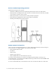
To connect to power
A. Connect both power cords to the VTS server.
B. Plug each power cord into a grounded electrical outlet. It is recommended that the cords be
routed to separate power sources for redundancy.
To connect to monitor, keyboard, and mouse
A. Connect one end of a VGA cable into the VGA port on the VTS server.
B. Connect the other end of the cable into the monitor or computer with terminal emulation.
C. If using a keyboard, connect it to a PS/2 or USB port on the VTS server.
D. If using a mouse, connect it to a PS/2 or USB port on the VTS server.
To connect the iLO port to the network
A. Connect one end of an Ethernet cable to the iLO port.
B. Connect the other end of the cable to the LAN or WAN switch.
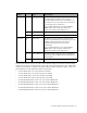
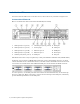
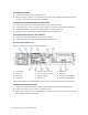
Connect the VT5900-K
Here is an illustration of the back of the VT5900-K:
The second 4Gb FC card (VT5900-FC4) shown in slot 2 is optional and may not be installed.
To connect to the host server
A. Connect one end of a Fibre optic cable to a Fibre Channel (FC) port on the VTS server.
B. Connect the other end of the cable to the host server.
C. Note the port number used on the VTS server. Later, you will have to set this port to target
mode using the VTS web interface.
1. Power plugs
2. PS/2 port
3. PS/2 port
4. Serial port
5. FC port (slot 3, port A)
6. FC port (slot 3, port B)
7. Ethernet ports
8. USB ports
9. Mgmt port
10. VGA port
11. FC port (slot 2, port A)
12. FC port (slot 2, port B)