
Virtual TapeServer 6.04.03 for NonStop Servers Quick Setup Guide

12 | Virtual TapeServer Quick Setup Guide
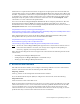
Connect the VT5900-L
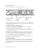
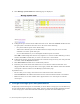
Here is an illustration of the back of the VT5900-L (base model):
An FC card (VT5900-FC4) may be installed in slot 5 (above slot 6). A FC card (VT5900-FC4) may
also be installed in slot 1 (above the fan and power plug on the left), replacing the P800 card that
is installed in the base model.
To connect to host servers using Fibre Channel
A. Connect one end of a Fibre optic cable to a Fibre Channel (FC) port on the VTS server.
B. Connect the other end of the cable to the host server.
C. If you are cabling multiple host servers to VTS, repeat steps A-B for each host server.
D. Note the port number used on the VTS server. Later, you will have to set this port to target
mode using the VTS web interface.
To connect to an external Fibre Channel disk array or external tape devices
A. Connect one end of a Fibre optic cable to the Fibre Channel (FC) port on the VTS server.
B. Connect the other end of the cable to the external disk array or tape drive or library.
C. If you are cabling to multiple tape devices, repeat steps A-B.
You may want to connect a second cable, to provide redundancy. When using the VT5917, for
example, active/active failover can be configured.
To connect to the network
Connect one end of an Ethernet cable to Ethernet port 1, which is the right-most port. (Port 1
corresponds to Eth0 in Linux.) Connect the other end of the cable to the LAN or WAN switch.
If Instant DR or AutoCopy is licensed, you may also want to connect to Ethernet port 2. (Port 2
corresponds to Eth1.) Performance on port 1 may be affected if you do not dedicate a port to
Instant DR or AutoCopy.
1. 4Gb FC ports (slot 2)
2. 4Gb FC ports (slot 3)
3. Power plugs
4. 4Gb FC ports (slot 6)
5. Ethernet ports 4 and 3
6. iLO port
7. Serial port
8. PS/2 ports
9. Ethernet ports 2 and 1
10. VGA port
11. USB ports