Virtual TapeServer for NonStop Servers Supplemental Installation Guide HP Part Number: 586323-002 Published: December 2009 Edition: All J06 release version updates (RVUs), all H06 RVUs, and all G06 RVUs
© Copyright 2009 Hewlett-Packard Development Company, L.P. Legal Notice Confidential computer software. Valid license from HP required for possession, use or copying. Consistent with FAR 12.211 and 12.212, Commercial Computer Software, Computer Software Documentation, and Technical Data for Commercial Items are licensed to the U.S. Government under vendor’s standard commercial license. The information contained herein is subject to change without notice.
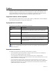
Contents Preface . . . . . . . . . . . . . . . . . . . . . . . . . . . . . . . . . . . . . . . . . . . . . . . . . . . . . . . . . . . . . . . . . . . . . . .v Supported release version updates . . . . . . . . . . . . . . . . . . . . . . . . . . . . . . . . . . . . . . . . . . . . . . . v Typographical conventions . . . . . . . . . . . . . . . . . . . . . . . . . . . . . . . . . . . . . . . . . . . . . . . . . . . . . v Related documentation . . . . . . . . . . . . . . . . . . . . . . . . . . . . . . . . .
iv | Contents
Preface Welcome to the Virtual TapeServer Supplemental Installation Guide. This guide provides additional configuration information for Virtual TapeServer (VTS), which should be used after completing the procedures in the Virtual TapeServer Quick Setup Guide and Virtual TapeServer Installation Guide. This guide is provided for HP personnel only.
vi | Preface
Installing GFS The Global File System (GFS) is an advanced feature that allows Linux servers to simultaneously read and write files on a single shared file system on a SAN. VTS is based on Linux, and GFS enables multiple VTS servers to access a shared set of pools and virtual tapes. The Event Management Service (EMS) can then automatically mount virtual tapes from the GFS pools as if they were separately mounted.
switch). Or, you can configure HP Integrated Lights-Out (iLO) to handle fencing. Refer to the following for more information about fencing: • Fencing overview — http://www.redhat.com/docs/en-US/Red_Hat_Enterprise_Linux/5.2/ html/Cluster_Suite_Overview/s2-fencing-overview-CSO.html • Configuring fencing devices with Conga (luci and ricci) — http://www.redhat.com/docs/enUS/Red_Hat_Enterprise_Linux/5.2/html/Cluster_Administration/s1-config-fence-devicesconga-CA.
7. GFS RPMs inadvertently remove SCSI target mode support. To address this and maintain correctly functioning virtual tape drives (VTDs), run the following command: /usr/local/tape/bin/mkinitrd.pl -f The VTS server is rebooted after this completes. 8. Repeat steps 1-7 on each server (node) that will be included in the cluster. Complete the next four steps (steps 9-12) on only one server (node) that will be included in the cluster.
d. Quit parted. quit 10. Perform LVM initialization of the device. /dev/sde1 is used as an example partition on the /dev/sde device. a. Create the physical volume by entering the following command: pvcreate /dev/sde1 b. Create the volume group by entering the following: vgcreate gfsvg1 /dev/sde1 c. Create the logical volume by entering the following command. The -l 100%FREE argument creates a logical volume using the entire volume group. lvcreate -l 100%FREE -n lv1 gfsvg1 d.
Metadata Areas Metadata Sequence No VG Access VG Status MAX LV Cur LV Open LV Max PV Cur PV Act PV VG Size PE Size Total PE Alloc PE / Size Free PE / Size VG UUID 1 2 read/write resizable 0 1 1 0 1 1 17.14 GB 4.00 MB 4388 4388 / 17.14 GB 0 / 0 lm4cH7-4wgq-s1VR-VNwc-pFC6-i54u-h5tKxk h.
Syncing... All Done 12. Start ricci and luci. For more information about these GFS services, refer to http://www.redhat.com/docs/ manuals/enterprise/RHEL-5-manual/en-US/RHEL510/Cluster_Administration/s1-startluci-ricci-conga-CA.html. These services must be configured in the cluster before you can mount the newly created GFS volume. Complete the following steps to start the services. a. Make sure that the luci system has a proper /etc/hosts file.
• Click Add another entry. • Enter each cluster member's name and root password, and click Submit. • Click the Cluster tab at top of the page. • Click Create a New Cluster. • Enter the same cluster name specified in step 11a. • Enter each system's fully qualified domain name and root password. • Select Use locally installed packages. • Make sure Enable Shared Storage Support is selected. • Click Submit. Although the interface states that the systems are rebooted, they are not. 13.
15. Complete the following steps on each cluster node to verify that all cluster nodes can access the GFS volumes, mount them, and access files written by other nodes. In the following steps, VAULT10 is used as the name of the vault. a. Configure the /etc/fstab file to automatically mount the file system when VTS restarts. Add a line to the file that is similar to the following: /dev/gfsvg1/lv1 /VAULT10 gfs defaults 0 0 b.
16. Verify fencing. Note These steps verify Brocade Fibre Channel fencing only. Before performing these steps, make sure you are not logged into the switch through Telnet. If you are logged in, the brocade fencing script will fails with an error similar to the following: /sbin/fence_brocade -a ip_addr -l username -n 2 -p password -o disable pattern match read eof at ./fence_brocade line 138 # echo $? 255 where ip_addr, username, and password is that of the Fibre Channel switch.
Troubleshooting This section describes how to verify the installation and troubleshoot any issues. 1. Verify that the appropriate services are enabled and started by entering the following commands: chkconfig cman on && service cman restart chkconfig clvmd on && service clvmd restart chkconfig ricci on && service ricci restart 2.
Here is an example of the output: Version: 6.0.1 Config Version: 5 Cluster Name: cma Cluster Id: 711 Cluster Member: Yes Cluster Generation: 64 Membership state: Cluster-Member Nodes: 2 Expected votes: 1 Total votes: 2 Quorum: 1 Active subsystems: 7 Flags: 2node Ports Bound: 0 11 Node name: 192.168.80.2 Node ID: 2 Multicast addresses: 239.192.2.201 Node addresses: 192.168.80.
12 | Installing GFS
Enabling Instant DR and AutoCopy Instant DR is an advanced software module (VT5907-A) that enables you to create and maintain identical copies of backup data on Virtual TapeServer (VTS) disk storage at one or more locations. In the event of a disaster, remote recovery operations can begin immediately using the backup data copy on a remote VTS site. VTS copies data to remote sites over a wide area network (WAN) TCP/IP connection.
Instant DR and AutoCopy features have distinct advantages that may be specific to individual sites or requirements. In general, Instant DR should be used if files do not change much from day to day. AutoCopy is best used if files change often throughout the day.
• It is very important that SSH communications flow though network connections from one VTS system to another. A single gigabit connection is used to handle the SSH data transfer and other communications between VTS systems. To prevent congestion, because of the high volume of traffic that can flow over a connection used for Instant DR or Autocopy, it is recommended that a completely separate gigabit subnet be used to connect VTS systems. Network speeds of less than a gigabit are not recommended.
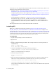
e. Select System →Network Device Control from pop-up list. The Network Device Control window is displayed. f. Select eth1 and click Configure. The Network Configuration window is displayed: g. Double-click eth1. h. Select Activate device when computer starts. i. Select Statically set IP Addresses. j. Provide the IP address, subnet mask, and default gateway. In this example, the boston VTS server is configured with IP address 10.10.2.145, subnet mask 255.255.255.0, and default gateway 10.10.2.1.
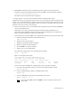
3. Set up the hosts file to configure aliases for each IP address of the VTS servers. a. Click the Hosts tab. b. Click New. c. Provide the IP address, hostname, and alias for the local VTS server. In this example, the following values are entered: • IP Address: 10.10.2.145 • Hostname: boston.mycompany.com • Aliases: boston d. Click OK.
e. Repeat these steps for each VTS site. In this example, after completing these steps for all VTS servers, the Hosts tab looks like this: f. Select File→Save. g. Click OK. h. Close the Network Configuration window. i. Select eth1. j. Click Deactivate. k. Click Activate. l. Select eth0. m. Click Deactivate. n. Click Activate. o. From the operating system GUI, select the Screen icon located at the bottom left-hand side of the window. A command prompt window is displayed. p.
4. Set up and edit the /home/bill/.rhosts file to define aliases for the IP addresses. Perform this step for each source VTS server. a. At the command prompt, log in. b. Become root: su c. Create the /home/bill/.rhosts file. d. Enter chown bill /home/bill/.rhosts to change the ownership of the file to bill. e. Enter chmod 600 /home/bill/.rhosts to set the privileges to read and write for bill. f. Open the /home/bill/.rhosts file for editing using a text editor, such as vi. g.
6. If you configured SSH and access to the bill account is restricted on the VTS servers, you must grant SSH access to the bill user for each VTS server. To do this, edit the /etc/ssh/ sshd_config file to add this line: AllowUsers vtsa bill@source_svr where source_svr is the IP address or hostname of the VTS server where the AutoCopy operation is originating.
Configuring TCP/IP security The need for security while using Instant DR becomes necessary if the communication link between VTS servers is not completely within your network. If you do not secure the link, others can gain access to the VTS operating system over TCP/IP from outside the corporate network. To tighten security, you can configure IP tables to block all TCP/IP traffic going to eth1 except SSH, RSH, and ICMP (ping and traceroute). To configure TCP/IP security 1.
• -A INPUT -p tcp -m state --state RELATED -j ACCEPT Allows connections that are of a related state only. A related connection is a new connection that is associated with an existing connection. • -A INPUT -p icmp -j ACCEPT Allows ICMP traffic (ping and traceroute). This is not required but is helpful when troubleshooting network issues. • -A INPUT -i eth1 -j REJECT --reject-with icmp-port-unreachable Rejects all traffic with the exception of the preceding rules.
Enabling Enterprise Integration and Migration Enterprise integration enables a backup management application server to read and write files to and from Virtual TapeServer (VTS). You can enable VTS to migrate virtual tapes to physical tapes. To configure VTS to automatically migrate virtual tapes, you must install a backup management application client on the VTS server and configure the VTSPolicy command in conjunction with the Event Management Service (EMS) on VTS.
application server from physical tape if the server requests access to a virtual tape that was erased or deleted. • VTS can request that the backup management application server perform a backup or restore. This request is generated when you manually initiate a migration. This request is issued using the backup management application command-line interface. VTS generates the backup management application command request, executing it on the VTS server.
e. Click Manage system limits. The Manage system limits page is displayed. f. Select the Physical checkbox that corresponds to the target bus and then click Set Limits. The VTS server automatically reboots. 2. Power down the VTS server and then cable the physical tape drive (through the SCSI converter as necessary) to the VTS server. Then, power on the physical tape drive and SCSI converter. 3. Power on the VTS server. 4.
[RelAdr=0] WBus16=1 Sync=1 Linked=0 [TranDis=0] Clocking=0x3 QAS=0 IUS=0 length=74 (0x4a) Peripheral device type: tape Vendor identification: CERTANCE Product identification: ULTRIUM 3 Product revision level: 1770 Product serial number: JD006D2 CmdQue=0 Repeat for each tape drive that was added. Configuring migration Be sure that the backup management application client is installed and configured on the VTS server. Refer to the backup management application documentation for more information.
Parameter Description Values Req’d? hsm_server For Backup Express, NetBackup, Networker, and CommVault Galaxy only: Hostname or IP address Yes Pool name Yes Pool names, separated by spaces Yes checksum, EOJ, or retention Yes checksum, EOJ, or retention Yes No Specifies the restore device. Name of the restore device. For Tivoli Storage Manager only: Path Yes Path No Integer, from 1-30 No Specifies the backup management application server hostname or IP address.
Parameter Description Values Req’d? hsm_policy For NetBackup only: Policy Yes The schedule name Yes Hostname or IP address Yes Backup set name Yes Policy name Yes YES or NO No Integer, from 0-999 No Integer No Specifies the backup policy. hsm_schedule For NetBackup only: Specifies the backup schedule. (Typically, a User schedule is specified.) hsm_client For CommVault Galaxy only: Specifies the hostname or IP address of the VTS server on which the CommVault client is installed.
Parameter Description Values Req’d? hsm_restore_period For Backup Express only: Value No YES or NO No Specifies how far back in time the backup management application should search its catalog for the file to be restored.
• NetBackup: hsm_enable='YES' hsm_product='NBP' hsm_policy='POLICY' hsm_schedule='USER' hsm_server='SERVER' ems_hsm_backup_notification='YES' • CommVault Galaxy hsm_enable='YES' hsm_product='CMV' hsm_server='stingray3' hsm_client='server42' hsm_backupset='server42_OnDemand' hsm_subclient='default' 4. Click SAVE. 5. Set the username and password for the backup management application. Note This step is required for CommVault Galaxy, Backup Express, and NetBackup only. a.
SCSI-to-Fibre Channel Adapter Upgrade This chapter provides instructions to replace one or more SCSI cards with the same number of VTS-supported Fibre Channel cards on the following VTS models: • VT5900-E, on the HP ProLiant DL385 G2 • VT5900-H, on the HP ProLiant DL385 G5 Refer to Upgrading a SCSI Adapter to a Fibre Channel Adapter on page 45 if you need to upgrade legacy hardware.
g. Click Supervisor Functions on the navigation pane. h. Click Block TapeServer Startup on the Supervisory Functions page. 2. Unmount all vaults, stop the Process Multi-Function (PMF) on the NonStop server, and shut down VTS. a. From a terminal window on VTS, log in. b. Become root: su c. Use the umount /VAULTxx command (where xx is the vault number) to unmount all vaults. Repeat this command for each vault on the system until all vaults are unmounted. d.
Here is a snapshot of the SCSI card after it is removed: g. After you install the Fibre Channel upgrade cards in the appropriate slots, make sure the blue clips are firmly seated and locked in place on each slot. Then, re-install the PCI Riser cage in the DL385 G2 chassis. Once aligned, firmly press the module into place. Re-tighten the two blue pull tabs on the PCI Riser cage. h. Place the top cover back in place and secure it.
6. Configure the new Fibre Channel bus(es) as virtual devices (targets). For each bus that you wish to configure for use as a virtual tape drive, complete these steps: a. Click Factory Setup on the navigation pane. b. When prompted, enter the login credentials. c. Click Factory Options and enter the login credentials again. d. Click Manage system limits. The Manage system limits page is displayed.
f. PCI Slot Bus Number Card Type Virtual Tape Name 5A 2 2G Fibre $VTAPE02 5B 3 2G Fibre $VTAPE03 Click Set Limits. 7. Reboot VTS. 8. Use the VTS web interface to reconfigure a virtual tape connection. After the Fibre Channel ports are configured as virtual devices, the final step in this process is to reconfigure the virtual tape connections. Virtual tape connections originally set up as SCSI need to be edited for use on a Fibre Channel bus.
36 | SCSI-to-Fibre Channel Adapter Upgrade
Hardware Information for Legacy Installations This chapter describes the hardware that was shipped for the Virtual TapeServer (VTS) 6.03.39, 6.03.41, 6.03.42, and 6.04 installations and that is supported in an upgraded environment. It also provides cabling and Fibre Channel upgrade procedures for the old hardware. Hardware overview For VTS installations that are upgrading to 6.04.02, the following hardware may be installed. Note Models shipped with 6.03.42 and 6.04 are still shipped with 6.04.
• Models VT5900-E and VT5900-G are built on an HP ProLiant DL385 G2 server: Two Fibre Channel cards are installed (for supporting VTDs) in model VT5900-G. Two SCSI cards are installed in model VT5900-E. SCSI converters Each SCSI converter converts high-voltage differential (HVD) Ultra160/SCSI-3 to low-voltage differential (LVD) Ultra-2 SCSI. It provides up to four converter circuits.
• VT5905 or VT5905-B, which are built on the StorageWorks MSA 1000 and provide a builtin 8-port Fibre Channel switch. The VT5905 provides 14 hard disk bays, and each hard disk provides 146GB of storage at 10,000rpm. Each hard drive in the VT5905-B provides 300GB disks. • VT5906 or VT5906-B, which are built on the StorageWorks Modular 4314 and available if additional storage was needed after purchasing and installing the VT5905 or VT5905-B. Up to two of these can be installed per VT5905 or VT5905-B.
Cabling and connecting VTS Cabling for the various VTS models is described in the following sections.
Connecting the HP ProLiant DL585 G1 (VT5900-A) The VT5900-A is a 4U (7 inch) chassis and provides 12 SCSI bus assignments, numbered 112. This model includes two dual-channel Fibre Channel cards, providing up to four connections to external storage.
Here is an illustration of the bus numbers on the back of the VT5900-A (DL585 G1): Here is an illustration of the HVD and LVD ports on the back of the SCSI converter: Connecting the HP ProLiant DL380 G4 (VT5900-B and VT5900-C) The VT5900-B and VT5900-C were built on a 2U (3.5 inch) chassis and provides four SCSI buses, numbered 0-3. The VT5900-C has a dual-channel Fibre Channel card but no DAT72 drive and is shipped with two (mirrored) 36GB SCSI drives, for use by the software only.
Here is an illustration of the HVD and LVD ports on the back of the SCSI converter: Connecting the HP ProLiant DL385 G2 (VT5900-E) The VT5900-E is built on a 2U (3.5 inch) chassis and provides four SCSI buses, numbered 0-3. A dual-channel 4Gbps Fibre Channel card is also provided for connection to the SAN. This base model allows the use of all four SCSI buses for connecting virtual tape drives (no ports on the 4Gbps Fibre Channel card can be used for virtual connections).
Connecting the HP ProLiant DL385 G2 (VT5900-G) The VT5900-G are built on a 2U (3.5 inch) chassis and provides up to four Fibre Channel buses, numbered 0-3. A dual-channel 4Gbps Fibre Channel card is also provided for connection to external storage (buses 4 and 5). This base model allows the use of four 2Gbps Fibre Channel buses for connecting virtual tape drives (no ports on the 4Gbps Fibre Channel card can be used for virtual connections). Here is an illustration of the slots on the back of the base model.
Upgrading a SCSI Adapter to a Fibre Channel Adapter SCSI-to-Fibre Channel Adapter Upgrade on page 31 provides instructions to replace one or more SCSI cards with the same number of VTS-supported Fibre Channel cards. Instructions for the 6.03.42 models are included in that appendix; refer to it for the steps required to replace a SCSI card.
6. Remove SCSI cards from the server as follows: Note This order must be followed or the upgrade will not work. Every HP ProLiant DL585 server has SCSI and Fibre Channel cards in the same physical slots. A Fibre Channel card is always in slots 5 and 6. You will see slot numbers on the chassis above each slot. These numbers are visible on the inside and outside of the chassis. The following order of SCSI card removal must be followed: a.
e. Remove the SCSI card in slot 7 and install the fifth Fibre Channel card in slot 7, if necessary. f. Remove the SCSI card in slot 8 and install the sixth Fibre Channel card in slot 8, if necessary. Here is a snapshot of the SCSI card after it is removed: 7. After you install all of the Fibre Channel upgrade cards in the appropriate slots, make sure the blue clips are firmly seated and locked in place on each slot. Then, re-install the shipping bracket and make sure the pull tab is secure. 8.
5. Look inside the ProLiant DL380 server to the back right-hand side where a pluggable module, called the PCI Riser cage, houses the SCSI and Fibre adapters. You will see a two round blue quick-release pull tabs that you need to open. Once loose, grasp the PCI Riser cage and pull up to remove it from the DL380 chassis. Refer to the diagrams on top of the PCI Riser cage if you have any questions about its removal.
The following order of SCSI card removal must be followed: a. Remove the SCSI card in slot 3 and install the first Fibre Channel card in slot 3. b. Remove the SCSI card in slot 2 and install the second Fibre Channel card in slot 2, if necessary. Here is a snapshot of the SCSI card after it is removed: 7. After you install all of the Fibre Channel upgrade cards in the appropriate slots, make sure the blue clips are firmly seated and locked in place on each slot.
50 | Hardware Information for Legacy Installations
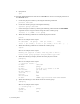
Advanced Options for Tape Connections If you click the Advanced link at the bottom of the Manage Tape Connections page, you can access pages that enable you to create, modify, and delete physical, logical, and virtual tapes. Here is a diagram of the components and their relationships: The virtual, logical, and physical tapes comprise a VTD. The virtual tape is the definition of the device that the host will see.
d. Click Add a new physical tape. The Add Physical Tape page is displayed. e. From the bus drop-down list, select the value that corresponds to the highest bus number available. In the example above, this value is 2. f. Select a target ID from the target drop-down list. If you are creating more than one VTD, select the value above the target noted in step 5b for subsequent VTDs. g. Leave the lun drop-down list set to 0. h. Leave the initiator drop-down list set to 7. i.
b. Click Add a new virtual tape. The Add A New Virtual Tape page is displayed. c. From the bus drop-down list, select the bus ID to which the host server is connected. To determine the bus ID, you must find the PCI slot number on the back of the VTS server module where the SCSI or Fibre Channel cable connects from the card to the target. Labels indicate the bus number for each port. d. From the target drop-down list, select the ID on which the virtual tape will respond.
This field is optional unless the host server is a NonStop BladeSystem. If you do not enter a serial number, the BTLI will be presented to the host as the serial number but not shown in the web interface. The default BTLI serial number is unique per VTS server but other VTS servers may create the same BTLI serial number. In an environment with more than one VTS server connected to a NonStop BladeSystem, specify serial numbers that are unique across the environment to avoid conflicts. k.
Index A E adding physical tape drive 24 attaching physical tape drives 24 AutoCopy configuring network settings 15 TCP/IP security 21 configuring SSH 19 enabling 13 ems_hsm_backup_notification parameter 29 enabling AutoCopy 13 Instant DR 13 external storage for legacy hardware 38 B backup management applications, See BMAs BMAs integration 23 bus-to-slot table 53 C cabling connection order VT5900-A 41 VT5900-B and VT5900-C 42 VT5900-E 43 VT5900-G 44 configuring automated migration 26 enterprise integrat
installing GFS 1 Instant DR configuring network settings 15 TCP/IP security 21 configuring SSH 19 enabling 13 internal storage for legacy hardware 38 L licensing migration 30 LUN, description 53 M Manage system limits page 25 migration configuration parameters 26 licensing 30 overview 23 MSA 1000 39 MSA 1500 38 O overview legacy hardware 37 migration 23 P physical tape drive, adding 24 R related documentation v S SCSI upgrading to Fibre Channel for legacy hardware 45 SCSI-to-Fibre Channel upgrade curr