
Virtual TapeServer 6.04.03 for NonStop Servers Supplemental Installation Guide


44 | Hardware Information for Legacy Installations
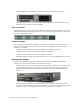
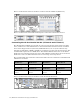
Connecting the HP ProLiant DL385 G2 (VT5900-G)
The VT5900-G are built on a 2U (3.5 inch) chassis and provides up to four Fibre Channel
buses, numbered 0-3. A dual-channel 4Gbps Fibre Channel card is also provided for
connection to external storage (buses 4 and 5). This base model allows the use of four 2Gbps
Fibre Channel buses for connecting virtual tape drives (no ports on the 4Gbps Fibre Channel
card can be used for virtual connections).
Here is an illustration of the slots on the back of the base model. If the P800 card is installed,
it is placed in slot 3 (below slot 4).
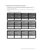
Modifying virtual tape connections
When modifying a virtual tape connection in VTS, you must define a virtual tape’s properties.
Refer to the Virtual TapeServer Installation Guide for an explanation of the properties and
instructions for modifying them. These following provides information needed when
modifying the bus ID for virtual tape connections on 6.03.39 and 6.03.41 hardware.
To determine the bus ID, you must find the PCI slot number on the back of the VTS server
module where the SCSI or Fibre Channel cable connects from the card to the target. Labels
indicate the bus number for each port.
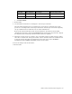
For legacy hardware, the bus IDs are as follows:
DL380 G4 (VT5900-B, VT5900-C)
PCI-X Slot Bus #
3 A 0
3 B 1
2 A 2
2 B 3
1 A 4
1 B 5