Quick Start Guide Virtual TapeServer for NonStop Servers Model: VT5900-H, VT5900-K, and VT5900-L, Release: 6.04.04 Part number: 628533-001 Virtual TapeServer (VTS) is a fully integrated virtual tape, hardware, and software solution. VTS allows host systems to read from and write to a local or SAN-attached file system. For every host connection to VTS, the host system “sees” a tape drive; the virtual tape drive emulates the type of tape drive specified during the initial installation and setup process.
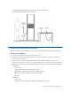
1 Prepare for installation To ensure that you are ready for deployment, complete the following tasks. Choose a location VTS can be mounted in a 19-inch rack near the host server.
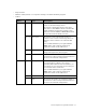
• Tape measure • Monitor and keyboard, or a computer running a terminal emulation program • Cables: Model # Type Description VT5900-H Up to 4 SCSI (HVD) To connect from the SCSI converter to the host server or external storage device. To connect to the SCSI converter, the cable must have a male MD68 connector. SCSI cable length is limited to 25 meters (82 feet). Note that four 2-meter VHDCI-to-MD68 HVD cables are provided with the SCSI converter.
Model # Type Description VT5900-L Up to 2 SCSI (HVD) To connect from the SCSI converter to the host server or external storage device. To connect to the SCSI converter, the cable must have a male MD68 connector. SCSI cable length is limited to 25 meters (82 feet). Note that four 2-meter VHDCI-to-MD68 HVD cables are provided with the SCSI converter. Up to 10 Fibre optic By default, you can connect to up to six host servers or external drives or libraries.
2 • Restraining any dangling items that can get caught in equipment. • Working in an ESD-protected environment: Unpack and identify the hardware Before mounting and cabling VTS, you must unpack the hardware and verify the box contents. Unpack all hardware A. Unpack all hardware and retain packing materials. B. Inspect the hardware and the contents of the box(es). If damage is apparent, contact the carrier and your vendor. C. Place hardware on a flat, stable work surface.
• • • • • HP ProLiant DL185 Generation 5 Server Installation Sheet • HP Virtual TapeServer Base Release 6.04.
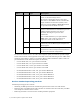
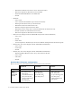
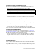
VT5900-H VT5900-K VT5900-L Additional Internal Storage Eight 300GB internal disks (VT5904-H) Six 1TB internal disks (VT5900-6TB) Not supported External Disk Storage P2000 MSA (one VT5930 controller with 12 2TB drives and up to three VT5931 expansion chassis, each with 12 2TB drives); maximum capacity per P2000 system is 96TB† Not supported P2000 MSA (one VT5930 controller with 12 2TB drives and up to three VT5931 expansion chassis, each with 12 2TB drives); maximum capacity per P2000 system is 96T
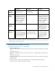
• VT5930, VT5931 (P2000 G3 Modular Smart Array) Download the HP StorageWorks 2000 Modular Smart Array racking instructions (c01505852.pdf), first edition (May 2008). Contact the HP Global Mission Critical Solution Center (GMCSC) if you encounter problems or need assistance. 4 Cable the VTS server You must cable the VTS server to the host server, then cable to any external storage devices. Connect the VT5900-H Here is an illustration of the back of the VT5900-H (base model): 1.
To connect to host servers through the SCSI converter Cable the host server to the SCSI converter and cable the SCSI converter to the VTS server: A. Connect one end of an LVD cable to an LVD bus (port) on the SCSI converter.
Instant DR or AutoCopy. Connect the other end of the cable to the LAN or WAN switch. (Note that you can also use port 2 for initial network configuration, as described below.) Note If you connect to more than one Ethernet port, it is recommended that you connect the ports to different subnets. To connect the iLO port to the network A. Connect one end of an Ethernet cable to the iLO port. B. Connect the other end of the cable to the LAN or WAN switch. To connect to power A.
Connect the VT5900-K Here is an illustration of the back of the VT5900-K: 1. Power plugs 5. FC port (slot 3, port A) 9. Mgmt port 2. PS/2 port 6. FC port (slot 3, port B) 10. VGA port 3. PS/2 port 7. Ethernet ports 11. FC port (slot 2, port A) 4. Serial port 8. USB ports 12. FC port (slot 2, port B) The second 4Gb FC card (VT5900-FC4) shown in slot 2 is optional and may not be installed.
Instant DR or AutoCopy. Connect the other end of the cable to the LAN or WAN switch. (Note that you can also use port 2 for initial network configuration, as described below.) Note If you connect to more than one Ethernet port, it is recommended that you connect the ports to different subnets. To connect to the management port for Lights-Out 100 support A. Connect one end of an Ethernet cable to the Mgmt port. B. Connect the other end of the cable to the LAN or WAN switch. To connect to power A.
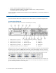
Connect the VT5900-L Here is an illustration of the back of the VT5900-L (base model): 1. SCSI ports (slot 4) 6. Ethernet ports 4 and 3 10. Ethernet ports 2 and 1 2. 4Gb FC ports (slot 2) 7. iLO port 11. VGA port 3. 4Gb FC ports (slot 3) 8. Serial port 12. USB ports 4. Power plugs 9. PS/2 ports 5. 4Gb FC ports (slot 6) The SCSI card installed in slot 4 is optional. An FC card (VT5900-FC4) may be installed in slot 5 (above slot 6).
To connect to host servers through the SCSI converter Cable the host server to the SCSI converter and cable the SCSI converter to the VTS server: A. Connect one end of an LVD cable to an LVD bus (port) on the SCSI converter.
Instant DR or AutoCopy. Connect the other end of the cable to the LAN or WAN switch. (Note that you can also use port 2 for initial network configuration, as described below.) Note If you connect to more than one Ethernet port, it is recommended that you connect the ports to different subnets. To connect the iLO port to the network A. Connect one end of an Ethernet cable to the iLO port. B. Connect the other end of the cable to the LAN or WAN switch. To connect to power A.
5 Power on the hardware Perform these steps in order to power all VTS hardware: A. Press the power button located on the front panel of the VTS server. The power button on the front panel changes from yellow to green, and the server module self-boots. Allow the VTS server to completely boot before proceeding. The console will display a login prompt when it is ready to proceed. B. Power up the VTS SCSI converter using the power switch on the rear panel, if necessary. C.
Here is an example of the PuTTY configuration: 3. For an Ethernet connection, specify the IP address of eth1 (1.1.1.1) on the VTS server, specify a port, and select a connection type. Here is an example of the PuTTY configuration: 4. Open the connection. B. At the command prompt, log in as root. When prompted, enter the current password, which is v-serial#_in_reverse (such as v-75001A if the serial number is A10057), and then set a new password.
C. To configure eth0 to use a static IP address, enter the following: netconfig -f eth0 -m static -i ip_address -n netmask -g gateway where ip_address is the management network interface address, netmask is the management network interface netmask, and gateway is the IP address for the gateway. You can skip this step if you plan to use DHCP. D. Set the list of DNS servers, domain, and hostname: 1. To set the list of DNS servers, enter the following: netconfig -d ip_address,ip_address,...
To set the system clock A. Set the timezone as follows: 1. Enter this command to launch the system-config-date tool: system-config-date The Timezone Selection screen is displayed: 2. Use the arrow keys on your keyboard to select the current timezone. 3. To configure the clock to use UTC, press the Tab key and then press the space bar to select the System clock uses UTC option. An asterisk (*) is displayed in the brackets when this option is selected. 4. Press the Tab key to select OK and then press Enter.
7 Configure storage space and path failover If deploying external storage for use with VTS, you must define a storage space on the disk array for use with the Linux operating system. Then, present a logical unit number (LUN) that refers to this storage space. Note that each LUN should not represent more than 5TB of space. Path failover is required when more than one physical or logical path exists between VTS and external disk storage, such as an MSA or HP StorageWorks Enterprise Virtual Array (EVA).
and the VTS web application server, through Secure Sockets Layer (SSL). This self-signed certificate may cause your browser to display a certificate warning for the following reasons: • Many browsers warn you when a web application employs a self-signed certificate. These certificates are not considered as secure as a certificate signed by a Certificate Authority. • When the VTS default self-signed certificate is created, a temporary hostname is used for the appliance.
Specifications • VT5900-H (DL385 G5) http://h18004.www1.hp.com/products/quickspecs/13012_na/13012_na.html • VT5900-K (DL185 G5) http://h18004.www1.hp.com/products/quickspecs/12864_na/12864_na.html • VT5900-L (DL380 G6) http://h18004.www1.hp.com/products/quickspecs/13234_na/13234_na.html • SCSI Converter http://www.rancho.com/Products.aspx?ID=2&Model=RTLVD-HVDRxER&CatID=1 http://www.rancho.com/DataSheets/RTLVD-xxxRxE_M.pdf • VT5930, VT5931 (P2000 G3 MSA) http://h18000.www1.hp.
Korea MIC Compliance Taiwan (BSMI) Compliance Japan (VCCI) Compliance This is a Class A product based on the standard or the Voluntary Control Council for Interference by Information Technology Equipment (VCCI). If this equipment is used in a domestic environment, radio disturbance may occur, in which case the user may be required to take corrective actions.
Laser Compliance This product may be provided with an optical storage device (that is, CD or DVD drive) and/or fiber optic transceiver. Each of these devices contains a laser that is classified as a Class 1 Laser 80 Safety and Compliance Product in accordance with US FDA regulations and the IEC 60825-1. The product does not emit hazardous laser radiation.
“HIGH LEAKAGE CURRENT, EARTH CONNECTION ESSENTIAL BEFORE CONNECTING SUPPLY” “HOHER ABLEITSTROM. VOR INBETRIEBNAHME UNBEDINGT ERDUNGSVERBINDUNG HERSTELLEN” “COURANT DE FUITE E’LEVE’. RACCORDEMENT A LA TERRE INDISPENSABLE AVANT LE RACCORDEMENT AU RESEAU” FUSE REPLACEMENT CAUTION – For continued protection against risk of fire, replace fuses only with fuses of the same type and the same rating. Disconnect power before changing fuses. Important Safety Information Safety information is located in two places.
| Virtual TapeServer Quick Start Guide