
Virtual TapeServer 6.04.04 for NonStop Servers Quick Start Guide

Virtual TapeServer Quick Start Guide | 13
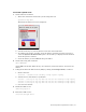
Connect the VT5900-L
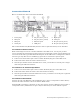
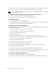
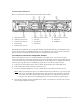
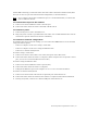
Here is an illustration of the back of the VT5900-L (base model):
The SCSI card installed in slot 4 is optional. An FC card (VT5900-FC4) may be installed in slot 5
(above slot 6). A FC card (VT5900-FC4) may also be installed in slot 1 (above the fan and power
plug on the left), replacing the P800 card that is installed in the base model.
To connect to host servers using Fibre Channel
When connecting host servers over Fibre Channel to the VTS server, use one port per host
server, if possible. If connecting more than one host server through a switch, ensure that the host
servers are of the same type. Each Fibre Channel port on the VTS server is configured to emulate
one host type only. Host servers of differing types must be connected to separate ports.
A. Connect one end of a Fibre optic cable to a Fibre Channel (FC) port on the VTS server.
B. Connect the other end of the cable to the host server.
C. If you are cabling multiple host servers to VTS, repeat steps A-B for each host server.
Note
When connecting host servers over Fibre Channel to the VTS server, use one port per
host server, if possible. If connecting more than one host server through a switch, be
aware that each Fibre Channel port on the VTS server is configured to emulate one
host type only. Host servers of differing types must be connected to separate ports.
D. Note the port number used on the VTS server. Later, you will have to set this port to target
mode using the VTS web interface.
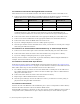
1. SCSI ports (slot 4)
2. 4Gb FC ports (slot 2)
3. 4Gb FC ports (slot 3)
4. Power plugs
5. 4Gb FC ports (slot 6)
6. Ethernet ports 4 and 3
7. iLO port
8. Serial port
9. PS/2 ports
10. Ethernet ports 2 and 1
11. VGA port
12. USB ports