Virtual TapeServer for NonStop Servers Supplemental Installation Guide HP Part Number: 628537-001 Published: July 2010 Edition: All J06 release version updates (RVUs), all H06 RVUs, and all G06 RVUs
© Copyright 2010 Hewlett-Packard Development Company, L.P. Legal Notice Confidential computer software. Valid license from HP required for possession, use or copying. Consistent with FAR 12.211 and 12.212, Commercial Computer Software, Computer Software Documentation, and Technical Data for Commercial Items are licensed to the U.S. Government under vendor’s standard commercial license. The information contained herein is subject to change without notice.
Contents Preface . . . . . . . . . . . . . . . . . . . . . . . . . . . . . . . . . . . . . . . . . . . . . . . . . . . . . . . . . . . . . . . . . . . . . . .v Supported release version updates . . . . . . . . . . . . . . . . . . . . . . . . . . . . . . . . . . . . . . . . . . . . . . . v Typographical conventions . . . . . . . . . . . . . . . . . . . . . . . . . . . . . . . . . . . . . . . . . . . . . . . . . . . . . v Related documentation . . . . . . . . . . . . . . . . . . . . . . . . . . . . . . . . .
iv | Contents
Preface Welcome to the Virtual TapeServer Supplemental Installation Guide. This guide provides additional configuration information for Virtual TapeServer (VTS), which should be used after completing the procedures in the Virtual TapeServer Quick Start Guide and Virtual TapeServer Installation Guide. This guide is provided for HP personnel only.
vi | Preface
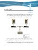
Installing GFS The Global File System (GFS) is an advanced feature that allows Linux servers to simultaneously read and write files on a single shared file system on a SAN. VTS is based on Linux, and GFS enables multiple VTS servers to access a shared set of pools and virtual tapes. The Event Management Service (EMS) can then automatically mount virtual tapes from the GFS pools as if they were separately mounted.
switch). Or, you can configure HP Integrated Lights-Out (iLO) to handle fencing. Refer to the following for more information about fencing: • Fencing overview — http://www.redhat.com/docs/en-US/Red_Hat_Enterprise_Linux/5.2/ html/Cluster_Suite_Overview/s2-fencing-overview-CSO.html • Configuring fencing devices with Conga (luci and ricci) — http://www.redhat.com/docs/enUS/Red_Hat_Enterprise_Linux/5.2/html/Cluster_Administration/s1-config-fence-devicesconga-CA.
Ignore any warnings that may be displayed. 5. Unmount and eject the DVD: umount /media/cdrom eject 6. Enter the following commands to disable clustering services that are included with the GFS but not used by VTS. Failure to disable these can cause the system to hang. chkconfig openais off && service openais stop chkconfig saslauthd off && service saslauthd stop If any of these commands returns a failure, it is not an error. It indicates that the process was not running. 7.
If the vault will be 2-4TB in size, complete these steps to partition the disk: a. Start the partition editor, which is an interactive program similar to fdisk: parted /dev/sda b. Create a GPT disk label, which is a GUID partition table: mklabel gpt c. Create a 4TB primary partition at the beginning of the disk: mkpart primary 0 4000G Note You can specify 100% instead of 4000G to create a partition that uses the entire disk. d. Quit parted. quit 10. Perform LVM initialization of the device.
Free PE Allocated PE PV UUID 0 4388 tTHBFt-6pqc-ILIY-Uis5-L8Yn-bvBu-SCN3MV g. Enter the following to view details about the volume group: vgdisplay Here is an example of the output: --- Volume group --VG Name System ID Format Metadata Areas Metadata Sequence No VG Access VG Status MAX LV Cur LV Open LV Max PV Cur PV Act PV VG Size PE Size Total PE Alloc PE / Size Free PE / Size VG UUID gfsvg1 lvm2 1 2 read/write resizable 0 1 1 0 1 1 17.14 GB 4.00 MB 4388 4388 / 17.
where -p lock_dlm argument sets the lock manager to DLM, -cluster_name specifies the cluster name, and journals specifies the number of journals to create, which should be the number of nodes plus two. b. When prompted, enter y to proceed. Output similar to the following is displayed: Device: Blocksize: Filesystem Size: Journals: Resource Groups: Locking Protocol: Lock Table: /dev/gfsvg1/lv1 4096 4394620 3 68 lock_dlm cma:01 Syncing... All Done 12. Start ricci and luci.
Note the URL given in the output; you will access it in the next step. d. Configure the cluster using the luci web interface: • Access the web interface by loading the URL given in the previous step in a web browser. • When prompted, accept the certificate permanently. • Click OK if a certificate domain mismatch warning is displayed. • Log in by entering the luci admin username and password. • Click Add a System. • Enter the fully qualified domain name of the GFS system.
c. Select GFS. d. For the name, enter the vault name (for example, VAULT10). e. For the mount point, enter the location where you want the vault to appear (for example, /VAULT10). f. For the device, enter the name of the device specified in step 11 (for example, /dev/ gfsvg1/lv1). g. Leave the options and filesystem ID blank. h. Click Submit. Because the LUN-to-device mapping can be different on each system, clvm logical volume names are globally unique. You cannot create duplicates.
e. Verify that files written by other VTS servers are visible by entering the following command: ls -al /VAULT10 Here is an example of the output: total 28 drwxr-xr-x 2 root root 3864 May 16 11:32 . drwxr-xr-x 4 root root 4096 May 15 17:59 .. -rw-r--r-- 1 root root 0 May 16 11:32 vtsdev27.commstor.crossroads.com After completing these steps on each node, this output lists each system's hostname in the vault directory. Be sure to delete these files after completing this installation procedure. 16.
18. Test fencing. In a separate window, enter the following command to view for fencing messages in the system log file: tail -f /var/log/messages Here is an example of the messages: May 15 19:10:25 VTS_svr fenced[10804]: VTS_svr2 not a cluster member after 0 sec post_fail_delay May 15 19:10:25 VTS_svr fenced[10804]: fencing node "VTS_svr2" May 15 19:10:26 VTS_svr fenced[10804]: fence "VTS_svr2" success 19.
If luci can see a node but indicates that ricci is not running, but the node shows ricci is running, output to the similar is displayed: luci[15356]: Unable to establish an SSL connection to 192.168.80.2:11111: ricci's certificate is not trusted Enter the following commands to remove luci: rpm -e luci rm -rf /var/lib/luci You may need to reinstall luci or re-import the cluster. The luci RPM is available on the GFS Install/Upgrade DVD.
12 | Installing GFS
Enabling Instant DR and AutoCopy Instant DR is an advanced software module (VT5907-A) that enables you to create and maintain identical copies of backup data on Virtual TapeServer (VTS) disk storage at one or more locations. In the event of a disaster, remote recovery operations can begin immediately using the backup data copy on a remote VTS site. VTS copies data to remote sites over a wide area network (WAN) TCP/IP connection.
Instant DR and AutoCopy features have distinct advantages that may be specific to individual sites or requirements. In general, Instant DR should be used if files do not change much from day to day. AutoCopy is best used if files change often throughout the day.
• It is very important that SSH communications flow though network connections from one VTS system to another. A single gigabit connection is used to handle the SSH data transfer and other communications between VTS systems. To prevent congestion, because of the high volume of traffic that can flow over a connection used for Instant DR or Autocopy, it is recommended that a completely separate gigabit subnet be used to connect VTS systems. Network speeds of less than a gigabit are not recommended.
d. From the operating system UI, click the Linux Start button at the bottom left-hand side of the window. e. Select System →Network Device Control from pop-up list. The Network Device Control window is displayed. f. Select eth1 and click Configure. The Network Configuration window is displayed: g. Double-click eth1. h. Select Activate device when computer starts. i. Select Statically set IP Addresses. j. Provide the IP address, subnet mask, and default gateway.
3. Set up the hosts file to configure aliases for each IP address of the VTS servers. a. Click the Hosts tab. b. Click New. c. Provide the IP address, hostname, and alias for the local VTS server. In this example, the following values are entered: • IP Address: 10.10.2.145 • Hostname: boston.mycompany.com • Aliases: boston d. Click OK.
e. Repeat these steps for each VTS site. In this example, after completing these steps for all VTS servers, the Hosts tab looks like this: f. Select File→Save. g. Click OK. h. Close the Network Configuration window. i. Select eth1. j. Click Deactivate. k. Click Activate. l. Select eth0. m. Click Deactivate. n. Click Activate. o. From the operating system GUI, select the Screen icon located at the bottom left-hand side of the window. A command prompt window is displayed. p.
4. Set up and edit the /home/bill/.rhosts file to define aliases for the IP addresses. Perform this step on the destination server for each source VTS server. a. At the command prompt, log in. b. Become root: su c. Create the /home/bill/.rhosts file. d. Enter chown bill /home/bill/.rhosts to change the ownership of the file to bill. e. Enter chmod 600 /home/bill/.rhosts to set the privileges to read and write for bill. f. Open the /home/bill/.rhosts file for editing using a text editor, such as vi. g.
Here is an example of the output: # SSH_AUTH_SOCK=/tmp/ssh-vHYet13854/agent.13854; export SSH_AUTH_SOCK; # SSH_AGENT_PID=13855; export SSH_AGENT_PID; c. Copy and paste the output to the command line, to run the commands. d. Generate an authorization key for SSH for the target server, to authorize remote access for the bill user: ssh-keygen -t rsa e. Press ENTER to save the file in the default location. This step creates the /home/bill/ .ssh/ directory. f. Press ENTER to skip the pass phrase. g.
Repeat these steps on each remote server. You should get similar results. Note RSH can be setup for one direction or multiple directions. If multiple directions are configured, these steps should be executed from the other direction. 9. Check the SSH connection, if you configured SSH. a. At the command prompt, log in. b. Become bill: su - bill c. At the command prompt, enter ssh user@server uptime. For example, on the Boston server, enter ssh bill@boston uptime.
--reject-with icmp-port-unreachable COMMIT Here is an explanation of these lines: • *filter Set the “filter” table as the table to be modified. • :INPUT ACCEPT [0:0] Sets the INPUT chain to a default value of ACCEPT. The [0:0] parameter is the count of packets and bytes to be set when establishing this chain. • :FORWARD ACCEPT [0:0] Sets the FORWARD chain to a default value of ACCEPT and its packet and byte counters to 0.
4. Enter the following commands: chkconfig iptables on service iptables restart At this point, all TCP/IP traffic is blocked except for SSH, RSH, and ICMP (ping and traceroute) traffic. 5. Repeat these steps on each source VTS server. Now, complete the configuration steps described in the Virtual TapeServer Operations and Administration Guide.
24 | Enabling Instant DR and AutoCopy
Enabling Enterprise Integration and Migration Enterprise integration enables a backup management application server to read and write files to and from Virtual TapeServer (VTS). You can enable VTS to migrate virtual tapes to physical tapes. To configure VTS to automatically migrate virtual tapes, you must install a backup management application client on the VTS server and configure the VTSPolicy command in conjunction with the Event Management Service (EMS) on VTS.
application server from physical tape if the server requests access to a virtual tape that was erased or deleted. • VTS can request that the backup management application server perform a backup or restore. This request is generated when you manually initiate a migration. This request is issued using the backup management application command-line interface. VTS generates the backup management application command request, executing it on the VTS server.
4.
3. Add the following parameters at the bottom of the file that is displayed: Parameter Description Values Req’d? hsm_enable Enables migration. YES or NO Yes TSM, LEG, BEX, NBP, or CMV Yes Hostname or IP address Yes Pool name Yes Pool names, separated by spaces Yes checksum, EOJ, or retention Yes checksum, EOJ, or retention Yes Name of the restore device. No Specifies the restore device.
Parameter Description Values Req’d? hsm_optfile_pool For Tivoli Storage Manager only: Path No Integer, from 1-30 No Policy Yes The schedule name Yes Hostname or IP address Yes Backup set name Yes Policy name Yes Specifies the path to the optfile file for a specific pool. This parameter overrides the hsm_optfile parameter for the pool.
Parameter Description Values Req’d? hsm_erase_after_ backup Enables VTS to automatically erase a virtual tape after it is successfully migrated. Only the tape data is erased; the metadata remains. YES or NO No Integer, from 0-999 No Integer No Value No YES or NO No Default value: NO hsm_joblog_ maxnum Specifies the maximum number of job log files to be retained. These files contain the output from each job. This value applies separately to backup and restore jobs.
Here are sample configurations for each backup management application: • Tivoli Storage Manager: hsm_enable='YES' hsm_product='TSM' hsm_optfile='dsm.opt' hsm_optfile_E1_HAL_10YEARS='/usr/opt/dsm.server10.
5. Set the username and password for the backup management application. Note This step is required for CommVault Galaxy, Backup Express, and NetBackup only. a. Click Supervisor Functions on the navigation pane. b. Click Manage Passwords. The following page is displayed: c. Select hsm from the drop-down list and configure a password. Click Help for complete instructions.
SCSI-to-Fibre Channel Adapter Upgrade This chapter provides instructions to replace one or more SCSI cards with the same number of VTS-supported Fibre Channel cards on the following VTS models: • VT5900-E, on the HP ProLiant DL385 G2 • VT5900-H, on the HP ProLiant DL385 G5 Refer to Upgrading a SCSI Adapter to a Fibre Channel Adapter on page 44 if you need to upgrade legacy hardware. Requires the View/Manage Configuration access right To replace SCSI cards with Fibre Channel cards and reconfigure VTS 1.
g. From the NonStop server, stop all virtual tape drives using the SCF STOP PMFname command. h. Power down all VTS SCSI converters using the switch on the rear of each unit. i. From a terminal window on VTS, enter shutdown now. 3. Remove the SCSI card(s) and install the Fibre Channel card(s). a. From the rear of the HP ProLiant DL385 G2 server, mark each SCSI cable with the port position to which it is attached. This will make it easier to reattach them to the correct SCSI ports later. b.
g. After you install the Fibre Channel upgrade cards in the appropriate slots, make sure the blue clips are firmly seated and locked in place on each slot. Then, re-install the PCI Riser cage in the DL385 G2 chassis. Once aligned, firmly press the module into place. Re-tighten the two blue pull tabs on the PCI Riser cage. h. Place the top cover back in place and secure it. Slide the HP DL385 G2 ProLiant server back into the rack and secure the two quick-disconnect screws on the front panel. i.
PCI Slot Bus Number Card Type Virtual Tape Name 3B N/A (left open for P800 controller card) 4A 0 2G Fibre $VTAPE00 4B 1 2G Fibre $VTAPE01 5A 2 2G Fibre $VTAPE02 5B 3 2G Fibre $VTAPE03 d. Click Submit. Confirm to reboot the server. 7. Use the VTS web interface to reconfigure a VTD. After the Fibre Channel ports are configured as virtual devices, the final step in this process is to reconfigure the VTDs. VTDs originally set up as SCSI need to be edited for use on a Fibre Channel port.
Hardware Information for Legacy Installations This chapter describes the hardware that was shipped for the Virtual TapeServer (VTS) 6.03.39, 6.03.41, 6.03.42, and 6.04 installations and that is supported in an upgraded environment. It also provides cabling and Fibre Channel upgrade procedures for the old hardware. Hardware overview For VTS installations that are upgrading to 6.04.04, the following hardware may be installed. Note Models shipped with 6.03.42 and 6.04 are still shipped with 6.04.
• Models VT5900-E and VT5900-G are built on an HP ProLiant DL385 G2 server: Two Fibre Channel cards are installed (for supporting VTDs) in model VT5900-G. Two SCSI cards are installed in model VT5900-E. SCSI converters Each SCSI converter converts high-voltage differential (HVD) Ultra160/SCSI-3 to low-voltage differential (LVD) Ultra-2 SCSI. It provides up to four converter circuits.
• VT5905 or VT5905-B, which are built on the StorageWorks MSA 1000 and provide a builtin 8-port Fibre Channel switch. The VT5905 provides 14 hard disk bays, and each hard disk provides 146GB of storage at 10,000rpm. Each hard drive in the VT5905-B provides 300GB disks. • VT5906 or VT5906-B, which are built on the StorageWorks Modular 4314 and available if additional storage was needed after purchasing and installing the VT5905 or VT5905-B. Up to two of these can be installed per VT5905 or VT5905-B.
Cabling and connecting VTS Cabling for the various VTS models is described in the following sections.
Connecting the HP ProLiant DL585 G1 (VT5900-A) The VT5900-A is a 4U (7 inch) chassis and provides 12 SCSI bus assignments, numbered 112. This model includes two dual-channel Fibre Channel cards, providing up to four connections to external storage.
Here is an illustration of the bus numbers on the back of the VT5900-A (DL585 G1): Here is an illustration of the HVD and LVD ports on the back of the SCSI converter: Connecting the HP ProLiant DL380 G4 (VT5900-B and VT5900-C) The VT5900-B and VT5900-C were built on a 2U (3.5 inch) chassis and provides four SCSI buses, numbered 0-3. The VT5900-C has a dual-channel Fibre Channel card but no DAT72 drive and is shipped with two (mirrored) 36GB SCSI drives, for use by the software only.
Here is an illustration of the HVD and LVD ports on the back of the SCSI converter: Connecting the HP ProLiant DL385 G2 (VT5900-E) The VT5900-E is built on a 2U (3.5 inch) chassis and provides four SCSI buses, numbered 0-3. A dual-channel 4Gbps Fibre Channel card is also provided for connection to the SAN. This base model allows the use of all four SCSI buses for connecting virtual tape drives (no ports on the 4Gbps Fibre Channel card can be used for virtual connections).
Connecting the HP ProLiant DL385 G2 (VT5900-G) The VT5900-G are built on a 2U (3.5 inch) chassis and provides up to four Fibre Channel buses, numbered 0-3. A dual-channel 4Gbps Fibre Channel card is also provided for connection to external storage (buses 4 and 5). This base model allows the use of four 2Gbps Fibre Channel buses for connecting virtual tape drives (no ports on the 4Gbps Fibre Channel card can be used for virtual connections). Here is an illustration of the slots on the back of the base model.
On the HP ProLiant DL585 G1 (VT5900-A) After completing step 2 on page 33, remove the SCSI card(s) and install the Fibre Channel card(s), as follows: 1. From the rear of the HP ProLiant DL585 server, mark each SCSI cable with the port position to which it is attached. This will make it easier to reattach them to the correct SCSI ports later. 2. Disconnect the ProLiant power cords as a precaution. Disconnect all SCSI cables from the SCSI adapters for easier access to the adapter cards. 3.
The following order of SCSI card removal must be followed: a. Remove the SCSI card in slot 3 and install the first Fibre Channel card in slot 3. b. Remove the SCSI card in slot 4 and install the second Fibre Channel card in slot 4, if necessary. c. Remove the SCSI card in slot 2 and install the third Fibre Channel card in slot 2, if necessary. d. Remove the SCSI card in slot 1 and install the fourth Fibre Channel card in slot 1, if necessary. e.
On the HP ProLiant DL380 G4 (VT5900-B and VT5900-C) After completing step 2 on page 33, remove the SCSI card(s) and install the Fibre Channel card(s), as follows: 1. From the rear of the HP ProLiant DL380 server, mark each SCSI cable with the port position to which it is attached. This will make it easier to reattach them to the correct SCSI ports later. 2. Disconnect the ProLiant power cords as a precaution. Disconnect all SCSI cables from the SCSI adapters for easier access to the adapter cards. 3.
The following order of SCSI card removal must be followed: a. Remove the SCSI card in slot 3 and install the first Fibre Channel card in slot 3. b. Remove the SCSI card in slot 2 and install the second Fibre Channel card in slot 2, if necessary. Here is a snapshot of the SCSI card after it is removed: 7. After you install all of the Fibre Channel upgrade cards in the appropriate slots, make sure the blue clips are firmly seated and locked in place on each slot.
Advanced Options for Tape Connections If you click the Advanced link at the bottom of the Manage Tape Connections page, you can access pages that enable you to create, modify, and delete physical, logical, and virtual tapes. Here is a diagram of the components and their relationships: The virtual, logical, and physical tapes comprise a VTD. The virtual tape is the definition of the device that the host will see.
d. Click Add a new physical tape. The Add Physical Tape page is displayed. e. From the bus drop-down list, select the value that corresponds to the highest bus number available. In the example above, this value is 2. f. Select a target ID from the target drop-down list. If you are creating more than one VTD, select the value above the target noted subsequent VTDs. g. Leave the lun drop-down list set to 0. h. Leave the initiator drop-down list set to 7. i.
b. Click Add a new virtual tape. The Add A New Virtual Tape page is displayed. c. From the bus drop-down list, select the bus ID to which the host server is connected. To determine the bus ID, you must find the PCI slot number on the back of the VTS server module where the SCSI or Fibre Channel cable connects from the card to the target. Labels indicate the bus number for each port. d. From the target drop-down list, select the ID on which the virtual tape will respond.
environment with more than one VTS server connected to a NonStop BladeSystem, specify serial numbers that are unique across the environment to avoid conflicts. k. Click Add Virtual Tape. 4. Add a new tape connection, as follows: a. Click Setup Tapes at the bottom of the page to display the Manage Tape Connections page. You can also click Advanced at the bottom of the Manage Tape Connections page, which is displayed when you click Manage Connections on the navigation pane. b. Click Add a tape connection.
Index A E adding physical tape drive 26 attaching physical tape drives 26 AutoCopy configuring network settings 15 TCP/IP security 21 configuring SSH 19 enabling 13 ems_hsm_backup_notification parameter 30 enabling AutoCopy 13 Instant DR 13 external storage for legacy hardware 38 F backup management applications, See BMAs BMAs, integration 25 bus-to-slot table 51 Fibre Channel upgrade for legacy hardware 44 procedure 33 VT5900-A 45 VT5900-B and VT5900-C 47 VT5900-E 34 C G cabling connection order V
Instant DR configuring network settings 15 TCP/IP security 21 configuring SSH 19 enabling 13 internal storage for legacy hardware 38 L licensing, migration 32 LUN, description 51 M migration configuration parameters 28 licensing 32 overview 25 MSA 1000 39 MSA 1500 38 O overview legacy hardware 37 migration 25 P physical tape drive, adding 26 R related documentation v S SCSI, upgrading to Fibre Channel for legacy hardware 44 SCSI-to-Fibre Channel upgrade, current models 33 SSH, configuring 19 T target