Virtual TapeServer for NonStop Servers Supplemental Installation Guide HP Part Number: 639680-001 Published: November 2010 Edition: All J06 release version updates (RVUs), all H06 RVUs, and all G06 RVUs
© Copyright 2010 Hewlett-Packard Development Company, L.P. Legal Notice Confidential computer software. Valid license from HP required for possession, use or copying. Consistent with FAR 12.211 and 12.212, Commercial Computer Software, Computer Software Documentation, and Technical Data for Commercial Items are licensed to the U.S. Government under vendor’s standard commercial license. The information contained herein is subject to change without notice.
Contents Preface . . . . . . . . . . . . . . . . . . . . . . . . . . . . . . . . . . . . . . . . . . . . . . . . . . . . . . . . . . . . . . . . . . . . . . .v Supported release version updates . . . . . . . . . . . . . . . . . . . . . . . . . . . . . . . . . . . . . . . . . . . . . . . v Typographical conventions . . . . . . . . . . . . . . . . . . . . . . . . . . . . . . . . . . . . . . . . . . . . . . . . . . . . . v Related documentation . . . . . . . . . . . . . . . . . . . . . . . . . . . . . . . . .
iv | Contents
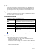
Preface Welcome to the Virtual TapeServer Supplemental Installation Guide. This guide provides additional configuration information for Virtual TapeServer (VTS), which should be used after completing the procedures in the Virtual TapeServer Quick Start Guide and Virtual TapeServer Configuration Guide. This guide is provided for HP personnel only.
vi | Preface
Installing GFS The Global File System (GFS) is an advanced feature that allows Linux servers to simultaneously read and write files on a single shared file system on a SAN. VTS is based on Linux, and GFS enables multiple VTS servers to access a shared set of pools and virtual tapes. The Event Management Service (EMS) can then automatically mount virtual tapes from the GFS pools as if they were separately mounted.
• Configuring fencing devices with Conga (luci and ricci) — http://www.redhat.com/docs/enUS/Red_Hat_Enterprise_Linux/5.2/html/Cluster_Administration/s1-config-fence-devicesconga-CA.html Note • When connecting to the Fibre Channel switch used for fencing, ensure that dual paths are not created when zoning is configured. All other Red Hat documentation — http://www.redhat.com/docs/manuals/csgfs/ The following topics are relevant: “Red Hat Cluster Suite Overview for RHEL5.
5. Unmount and eject the DVD: umount /media/cdrom eject 6. Enter the following commands to disable clustering services that are included with the GFS but not used by VTS. Failure to disable these can cause the system to hang. chkconfig openais off && service openais stop chkconfig saslauthd off && service saslauthd stop If any of these commands returns a failure, it is not an error. It indicates that the process was not running. 7. GFS RPMs inadvertently remove SCSI target mode support.
If the vault will be 2-4TB in size, complete these steps to partition the disk: a. Start the partition editor, which is an interactive program similar to fdisk: parted /dev/sde b. Create a GPT disk label, which is a GUID partition table: mklabel gpt c. Create a 4TB primary partition at the beginning of the disk: mkpart primary 0 4000G Note You can specify 100% instead of 4000G to create a partition that uses the entire disk. d. Quit parted. quit 10. Perform LVM initialization of the device.
Free PE Allocated PE PV UUID 0 4388 tTHBFt-6pqc-ILIY-Uis5-L8Yn-bvBu-SCN3MV g. Enter the following to view details about the volume group: vgdisplay Here is an example of the output: --- Volume group --VG Name System ID Format Metadata Areas Metadata Sequence No VG Access VG Status MAX LV Cur LV Open LV Max PV Cur PV Act PV VG Size PE Size Total PE Alloc PE / Size Free PE / Size VG UUID gfsvg1 lvm2 1 2 read/write resizable 0 1 1 0 1 1 17.14 GB 4.00 MB 4388 4388 / 17.
11. Create the GFS file system: a. Enter the following command. Note that any data that may reside on the logical volume (dev/gfsvg1/lv1 is used as an example) is destroyed. gfs_mkfs -p lock_dlm -t cluster_name:gfs01 -j journals /dev/ gfsvg1/lv1 where -p lock_dlm argument sets the lock manager to DLM, -cluster_name specifies the cluster name, and journals specifies the number of journals to create, which should be the number of nodes plus two. b. When prompted, enter y to proceed.
c. On one (and only one) of the cluster servers, configure and start the luci service. Red Hat recommends configuring luci on a non-cluster node. It will function properly on a cluster node, though web connectivity is lost while the system is rebooting. If the luci node goes down, the cluster cannot be administered with luci. luci_admin init When prompted, enter a new password. Then, restart the luci service: service luci restart Note the URL given in the output; you will access it in the next step. d.
h. Enter the corresponding password. Consult your SAN administrator for this information. i. Enter the port of the Fibre Channel switch. Consult your SAN administrator for this information. j. Click Update. Repeat these steps for each node in the cluster. 14. Add GFS storage to the cluster: a. In left-hand column of the web interface, under the cluster name, click Resources. b. Click Add a resource. c. Select GFS. d. For the name, enter the vault name (for example, VAULT10). e.
c. Enter the following command to verify that there is free space on the mounted GFS file system. df -h /VAULT10 Here is an example of the output: Filesystem /dev/mapper/gfsvg1-lv1 Size Used Avail Use% Mounted on 17G 36K 17G /VAULT10 1% d. Enter the following command to verify that you can write to the mounted GFS file system. touch /VAULT10/`hostname` e.
d. From the command line, enter the following: tail -f /var/log/messages Here is an example of the output: May 15 19:06:19 VTS_svr fence_node[28881]: Fence of "VTS_svr2" was successful 18. Test fencing.
5. Mount the vault by entering this command: mount /dev/gfsvg1/gfslv1 /VAULT10 6. If luci will not start or restart, enter the following: service luci start or service luci restart If luci can see a node but indicates that ricci is not running, but the node shows ricci is running, output to the similar is displayed: luci[15356]: Unable to establish an SSL connection to 192.168.80.
12 | Installing GFS
Enabling and Configuring BMA Integration and Migration BMA integration enables a backup management application server to read and write files to and from Virtual TapeServer (VTS). You can then enable VTS to export, or “migrate”, virtual tapes to physical tapes using an attached external tape device.
process and maintains a database of the backup files including a list of physical tapes to which the data was written. The backup management application server also controls the tape library. If VTS deletes or erases a virtual tape, the backup management application administrator must restore the virtual tape, when necessary.
Parameter Description Values Req’d? hsm_product Identifies the backup management application: TSM, LEG, BEX, NBP, or CMV Yes Hostname or IP address of the VTS server Yes Pool name Yes Pool names, separated by spaces Yes checksum, EOJ, or retention Yes checksum, EOJ, or retention Yes Name of the restore device. No Specifies the restore device.
Parameter Description Values Req’d? hsm_put_batch_size For Tivoli Storage Manager only: Integer, from 1-30 No Policy Yes The schedule name Yes Hostname or IP address Yes Backup set name Yes Policy name Yes YES or NO No Specifies the maximum number of virtual tapes to lock and migrate at a time, thereby creating batches of tapes to migrate. This parameter is optional and set to 0 by default, which causes VTS to lock all target virtual tapes until the migration is complete.
Parameter Description Values Req’d? hsm_joblog_ maxnum Specifies the maximum number of job log files to be retained. These files contain the output from each job. This value applies separately to backup and restore jobs. If set to zero, no logs are retained. Integer, from 0-999 No Integer No Value No YES or NO No Default value: 20 hsm_summary_limit Specifies the number of lines retained in the log file, which records the command used to invoke each backup or restore job.
• Networker: hsm_enable='YES' hsm_product='LEG' hsm_pool='POOL' hsm_server='SERVER' ems_hsm_backup_notification='YES' • Backup Express: hsm_enable='YES' hsm_product='BEX' hsm_server='lab-bex' hsm_backup_pools='MEDIAPOOL DLT DEVICEPOOL' hsm_backup_options='CHECKSUM Y; EOJ_ACTION U; RETENTION 999;' hsm_backup_options_LABELED='CHECKSUM Y; EOJ_ACTION U; RETENTION 999;' hsm_backup_options_CADE='CHECKSUM Y; EOJ_ACTION U; RETENTION 999;' ems_hsm_backup_notification='YES' hsm_restore_period='90d' • NetBackup:
5. Set the username and password for the backup management application. Note This step is required for CommVault Galaxy, Backup Express, and NetBackup only. a. Click Supervisor Functions on the navigation pane. b. Click Manage Passwords. The following page is displayed: c. Select hsm from the drop-down list and configure a password. Click Help for complete instructions.
20 | Enabling and Configuring BMA Integration and Migration
Enabling and Configuring Data Replication Data Replication is a advanced software feature that enables you to back up data to remote Virtual TapeServer (VTS) servers. This feature is implemented as Instant DR and AutoCopy. VTS copies data to remote sites over a wide area network (WAN) TCP/IP connection. Virtual tapes on the originating (source) VTS server are transmitted to the remote (target) VTS server.
• SSH must be configured on all VTS servers if you want to secure data when copying data to remote locations (for Instant DR). Also, it must be configured on all VTS servers involved in AutoCopy operations. SSH must be configured for Protocol 2 RSA or DSA encryption using Public Key Identification. Public Key Identification requires that the sender’s Public Key be installed in the specific authorized_keys file on the receiver VTS system.
longer than copying an entire file. You may also rely on AutoCopy for synchronizing data. See Overview of AutoCopy below to determine if AutoCopy is a better solution for your needs. If Instant DR is licensed, you must enable licensing by entering the license key as described in the Virtual TapeServer Configuration Guide. Then, you can create new Instant DR backup schemes as well as launch and monitor the remote synchronization processes.
Instant DR and AutoCopy features have distinct advantages that may be specific to individual sites or requirements. In general, Instant DR should be used if files do not change much from day to day. AutoCopy is best used if files change often throughout the day.
Configuring network settings The following steps use two sites as an example of enabling Data Replication between two sites, Boston and Los Angeles, connected by a wide area network (WAN): To configure network settings 1. Verify that the hostname, IP address, and gateway are configured on each VTS server in the environment. Refer to the Quick Start Guide for more information. 2.
4. Set up and authorize secure shell (SSH) if you are configuring VTS for AutoCopy or if you wish to secure communication for Instant DR. a. At the command prompt, become bill: su - bill b. Export the SSH socket by entering this command: ssh-agent Here is an example of the output: SSH_AUTH_SOCK=/tmp/ssh-vHYet13854/agent.13854; export SSH_AUTH_SOCK; SSH_AGENT_PID=13855; export SSH_AGENT_PID; c. Copy and paste the output to the command line, to run the commands. d.
c. At the command prompt, enter ssh user@server uptime. For example, on the Boston server, enter ssh bill@boston uptime. The first time you enter an ssh command, a message similar to the following is displayed: The authenticity of host 'server_name (IP_addr)' can't be established. RSA key fingerprint is 5f:10:3c:47:78:8f:e3:28:9d:ab:6b:34:ed:d1:e4:08. Are you sure you want to continue connecting (yes/no)? Enter yes. d. Repeat these steps on each VTS server.
• :FORWARD ACCEPT [0:0] Sets the FORWARD chain to a default value of ACCEPT and its packet and byte counters to 0. • :OUTPUT ACCEPT [0:0] Sets the OUTPUT chain to a default value of ACCEPT and its packet and byte counters to 0. • -A INPUT -i eth1 -p tcp -m tcp --dport 22 -j ACCEPT Allows connections on port 22 (SSH). • -A INPUT -i eth1 -p tcp -m tcp --dport 514 -j ACCEPT -A INPUT -i eth1 -p udp -m udp --dport 514 -j ACCEPT Allow RSH connections on UDP and TCP port 514.
Configuring AutoCopy Note A default configuration file is defined for each VTS server. To override the default settings, you must define settings as described below. Requires the Edit Configuration File access right To modify the VTS configuration file to configure AutoCopy 1. Enable Data Replication licensing as described in Enabling Licensed Features on page 15. 2. Click Supervisor Functions on the navigation pane. 3. Click Edit Configuration File. 4.
Parameter Description Values autocopy_target_ poolname Specifies the target of the copy operation for the pool specified by poolname. Specify this parameter for each pool listed by the autocopy_pools parameter. VTS system name, such as server42 • You can set this parameter to a target VTS system name; in this case, the pool is copied to the same path on the target server. Ensure that an identically named vault exists on the target system.
Or: autocopy_enable='YES' autocopy_pools='DR1 DR2' autocopy_target_DR1='SVR08' autocopy_target_DR2='SVR08:/VAULT00/DR2_AU' 5. Click SAVE. 6. Restart the TapeServer process on the Supervisory Functions page.
32 | Enabling and Configuring Data Replication
SCSI-to-Fibre Channel Adapter Upgrade This chapter provides instructions to replace one or more SCSI cards with the same number of VTS-supported Fibre Channel cards on the following VTS models: • VT5900-E, on the HP ProLiant DL385 G2 • VT5900-H, on the HP ProLiant DL385 G5 Refer to Upgrading a SCSI Adapter to a Fibre Channel Adapter on page 44 if you need to upgrade legacy hardware. Requires the View/Manage Configuration access right To replace SCSI cards with Fibre Channel cards and reconfigure VTS 1.
g. From the NonStop server, stop all virtual tape drives using the SCF STOP PMFname command. h. Power down all VTS SCSI converters using the switch on the rear of each unit. i. From a terminal window on VTS, enter shutdown now. 3. Remove the SCSI card(s) and install the Fibre Channel card(s). a. From the rear of the HP ProLiant DL385 G2 server, mark each SCSI cable with the port position to which it is attached. This will make it easier to reattach them to the correct SCSI ports later. b.
g. After you install the Fibre Channel upgrade cards in the appropriate slots, make sure the blue clips are firmly seated and locked in place on each slot. Then, re-install the PCI Riser cage in the DL385 G2 chassis. Once aligned, firmly press the module into place. Re-tighten the two blue pull tabs on the PCI Riser cage. h. Place the top cover back in place and secure it. Slide the HP DL385 G2 ProLiant server back into the rack and secure the two quick-disconnect screws on the front panel. i.
PCI Slot Bus Number Card Type Virtual Tape Name 3B N/A (left open for P800 controller card) 4A 0 2G Fibre $VTAPE00 4B 1 2G Fibre $VTAPE01 5A 2 2G Fibre $VTAPE02 5B 3 2G Fibre $VTAPE03 d. Click Submit. Confirm to reboot the server. 7. Use the VTS web interface to reconfigure a VTD. After the Fibre Channel ports are configured as virtual devices, the final step in this process is to reconfigure the VTDs. VTDs originally set up as SCSI need to be edited for use on a Fibre Channel port.
Hardware Information for Legacy Installations This chapter describes the hardware that was shipped for the Virtual TapeServer (VTS) 6.03.39, 6.03.41, 6.03.42, and 6.04 installations and that is supported in an upgraded environment. It also provides cabling and Fibre Channel upgrade procedures for the old hardware. Hardware overview For VTS installations that are upgrading to 6.04.05, the following hardware may be installed. Note Models shipped with 6.03.42 and 6.04 are still shipped with 6.04.
• Models VT5900-E and VT5900-G are built on an HP ProLiant DL385 G2 server: Two Fibre Channel cards are installed (for supporting VTDs) in model VT5900-G. Two SCSI cards are installed in model VT5900-E. SCSI converters Each SCSI converter converts high-voltage differential (HVD) Ultra160/SCSI-3 to low-voltage differential (LVD) Ultra-2 SCSI. It provides up to four converter circuits.
• VT5905 or VT5905-B, which are built on the StorageWorks MSA 1000 and provide a builtin 8-port Fibre Channel switch. The VT5905 provides 14 hard disk bays, and each hard disk provides 146GB of storage at 10,000rpm. Each hard drive in the VT5905-B provides 300GB disks. • VT5906 or VT5906-B, which are built on the StorageWorks Modular 4314 and available if additional storage was needed after purchasing and installing the VT5905 or VT5905-B. Up to two of these can be installed per VT5905 or VT5905-B.
Cabling and connecting VTS Cabling for the various VTS models is described in the following sections.
Connecting the HP ProLiant DL585 G1 (VT5900-A) The VT5900-A is a 4U (7 inch) chassis and provides 12 SCSI port assignments, numbered 112. This model includes two dual-channel Fibre Channel cards, providing up to four connections to external storage.
Here is an illustration of the port numbers on the back of the VT5900-A (DL585 G1): Here is an illustration of the HVD and LVD ports on the back of the SCSI converter: Connecting the HP ProLiant DL380 G4 (VT5900-B and VT5900-C) The VT5900-B and VT5900-C were built on a 2U (3.5 inch) chassis and provides four SCSI ports, numbered 0-3. The VT5900-C has a dual-channel Fibre Channel card but no DAT72 drive and is shipped with two (mirrored) 36GB SCSI drives, for use by the software only.
Here is an illustration of the HVD and LVD ports on the back of the SCSI converter: Connecting the HP ProLiant DL385 G2 (VT5900-E) The VT5900-E is built on a 2U (3.5 inch) chassis and provides four SCSI ports, numbered 0-3. A dual-channel 4Gbps Fibre Channel card is also provided for connection to the SAN. This base model allows the use of all four SCSI ports for connecting virtual tape drives (no ports on the 4Gbps Fibre Channel card can be used for virtual connections).
Connecting the HP ProLiant DL385 G2 (VT5900-G) The VT5900-G are built on a 2U (3.5 inch) chassis and provides up to four Fibre Channel ports, numbered 0-3. A dual-channel 4Gbps Fibre Channel card is also provided for connection to external storage (ports 4 and 5). This base model allows the use of four 2Gbps Fibre Channel ports for connecting virtual tape drives (no ports on the 4Gbps Fibre Channel card can be used for virtual connections). Here is an illustration of the slots on the back of the base model.
On the HP ProLiant DL585 G1 (VT5900-A) After completing step 2 on page 33, remove the SCSI card(s) and install the Fibre Channel card(s), as follows: 1. From the rear of the HP ProLiant DL585 server, mark each SCSI cable with the port position to which it is attached. This will make it easier to reattach them to the correct SCSI ports later. 2. Disconnect the ProLiant power cords as a precaution. Disconnect all SCSI cables from the SCSI adapters for easier access to the adapter cards. 3.
The following order of SCSI card removal must be followed: a. Remove the SCSI card in slot 3 and install the first Fibre Channel card in slot 3. b. Remove the SCSI card in slot 4 and install the second Fibre Channel card in slot 4, if necessary. c. Remove the SCSI card in slot 2 and install the third Fibre Channel card in slot 2, if necessary. d. Remove the SCSI card in slot 1 and install the fourth Fibre Channel card in slot 1, if necessary. e.
On the HP ProLiant DL380 G4 (VT5900-B and VT5900-C) After completing step 2 on page 33, remove the SCSI card(s) and install the Fibre Channel card(s), as follows: 1. From the rear of the HP ProLiant DL380 server, mark each SCSI cable with the port position to which it is attached. This will make it easier to reattach them to the correct SCSI ports later. 2. Disconnect the ProLiant power cords as a precaution. Disconnect all SCSI cables from the SCSI adapters for easier access to the adapter cards. 3.
The following order of SCSI card removal must be followed: a. Remove the SCSI card in slot 3 and install the first Fibre Channel card in slot 3. b. Remove the SCSI card in slot 2 and install the second Fibre Channel card in slot 2, if necessary. Here is a snapshot of the SCSI card after it is removed: 7. After you install all of the Fibre Channel upgrade cards in the appropriate slots, make sure the blue clips are firmly seated and locked in place on each slot.
Index A E AutoCopy configuring TCP/IP security 27 configuring SSH 26 enabling 23 overview 23 parameters in configuration file 29 autocopy_enable parameter 29 autocopy_pools parameter 29 autocopy_target_anypool parameter 30 autocopy_target_poolname parameter 30 ems_hsm_backup_notification parameter 17 enabling AutoCopy 23, 29 Instant DR 22 external storage for legacy hardware 38 F B Fibre Channel upgrade for legacy hardware 44 procedure 33 VT5900-A 45 VT5900-B and VT5900-C 47 VT5900-E 34 backup manage
I installing GFS 1 Instant DR configuring TCP/IP security 27 configuring SSH 26 enabling 22 internal storage for legacy hardware 38 L licensing migration 19 M migration configuration parameters 14 licensing 19 overview 13 MSA 1000 39 MSA 1500 38 O overview legacy hardware 37 migration 13 R related documentation v S SCSI, upgrading to Fibre Channel for legacy hardware 44 SCSI-to-Fibre Channel upgrade current models 33 SSH, configuring 26 T typographical conventions v V virtual tape connections, config