Virtual TapeServer for NonStop Servers Configuration Guide HP Part Number: 690174-001 Published: February 2012 Edition: All J06 release version updates (RVUs), all H06 RVUs, and all G06 RVUs
© Copyright 2012 Hewlett-Packard Development Company, L.P. Legal Notice Confidential computer software. Valid license from HP required for possession, use or copying. Consistent with FAR 12.211 and 12.212, Commercial Computer Software, Computer Software Documentation, and Technical Data for Commercial Items are licensed to the U.S. Government under vendor’s standard commercial license. The information contained herein is subject to change without notice.
Contents Preface . . . . . . . . . . . . . . . . . . . . . . . . . . . . . . . . . . . . . . . . . . . . . . . . . . . . . . . . . . . . . . . . . . . . . vii About this guide . . . . . . . . . . . . . . . . . . . . . . . . . . . . . . . . . . . . . . . . . . . . . . . . . . . . . . . . . . . . . vii Supported release version updates . . . . . . . . . . . . . . . . . . . . . . . . . . . . . . . . . . . . . . . . . . . . . . vii Audience . . . . . . . . . . . . . . . . . . . . . . . . . . . . . . . . . . . .
9 Enabling and Configuring Data Replication . . . . . . . . . . . . . . . . . . . . . . . . . . . . . . . . . . . . .39 Configure data partitions on target servers . . . . . . . . . . . . . . . . . . . . . . . . . . . . . . . . . . . . . . . 40 Enabling Data Replication licensing . . . . . . . . . . . . . . . . . . . . . . . . . . . . . . . . . . . . . . . . . . . . . 41 Configuring source and target settings . . . . . . . . . . . . . . . . . . . . . . . . . . . . . . . . . . . . . . . . . .
15 Configuring User Accounts . . . . . . . . . . . . . . . . . . . . . . . . . . . . . . . . . . . . . . . . . . . . . . . . . . . .97 Managing operating system accounts . . . . . . . . . . . . . . . . . . . . . . . . . . . . . . . . . . . . . . . . . . . . 97 Using the vtsa account . . . . . . . . . . . . . . . . . . . . . . . . . . . . . . . . . . . . . . . . . . . . . . . . . . . . 97 Adding accounts . . . . . . . . . . . . . . . . . . . . . . . . . . . . . . . . . . . . . . . . . . . . . . . . . . . . .
Message IDs . . . . . . . . . . . . . . . . . . . . . . . . . . . . . . . . . . . . . . . . . . . . . . . . . . . . . . . . Message text . . . . . . . . . . . . . . . . . . . . . . . . . . . . . . . . . . . . . . . . . . . . . . . . . . . . . . . . Export log . . . . . . . . . . . . . . . . . . . . . . . . . . . . . . . . . . . . . . . . . . . . . . . . . . . . . . . . . . . . . . Scan/Cleanup log files . . . . . . . . . . . . . . . . . . . . . . . . . . . . . . . . . . . . . . . . . . . . . . . . . . . .
Preface Welcome to the Configuration Guide. VTS offers complete disaster recovery capabilities. As a primary repository for data center backups, VTS can also be used as secondary tiered storage for replicated data to meet disaster recovery requirements. About this guide The Configuration Guide is designed to help you configure VTS and then accomplish the necessary tasks for using virtual media to store and retrieve data. This guide provides procedures for all tasks you must perform to start using VTS.
This icon is used throughout the guide to note the access right(s) required to perform the procedure that follows. Related documentation In addition to this guide, the following documentation is provided: • Quick Start Guide, which provides instructions for installing the hardware and configuring VTS on the network.
Introduction Tape remains the most practical solution for removable storage, and it is often required by regulatory agencies to be archived and stored offsite. However, as the cost of commodity disk storage has decreased, many enterprises view disk-based backup solutions as a feasible alternative to tape-based backup.
VTS delivers reliable, scalable, and high performance virtual tape for backup, restore, Transaction Management Facility (TMF), archive, and data recovery operations. You can deploy VTS to simplify and streamline traditional tape operations, reduce costs for storage hardware and tape media, automate backup and restore operations, and increase flexibility in managing backed-up data. The virtual environment The basic building blocks of VTS are vaults, pools, virtual tape drives, and virtual tapes.
needed, it can be discarded just like a physical tape. A virtual tape is synonymous with a file in a directory. Overview of features The heart of VTS is a middleware tape emulation engine that enables VTS to emulate tape storage to host servers and provides backup storage for the data on industry standard, lowcost disk arrays. Data stored in VTS can later be copied to real tape media for archival storage or disaster recovery if long-term backup copies are required.
Optional features that further enhance the benefits of VTS include the following: • Global File System (GFS) support — Offers enhanced access to shared vaults and eliminates single points of failure by deploying multiple VTS systems into a set of clustered nodes. In the event of a failure, GFS enables any active VTS system in the cluster to have access to the data, ensuring uninterrupted service to host systems.
Overview of Tasks After completing the procedures provided in the Virtual TapeServer Quick Start Guide, you can continue the initial configuration of the Virtual TapeServer (VTS) server. Then, you can use VTS to manage your virtual media. The following outlines the general tasks that you must complete to configure VTS and perform day-to-day tasks to maintain VTS. Many of these procedures for the tasks are now provided in the online help. To configure the VTS server 1.
11. Configure access control to grant or limit access to specific VTS functions. See Configuring User Accounts on page 97. 12. Configure the user interface as described in Configuring Web Interface Preferences on page 115. 13. Write labels to the virtual tapes from the host server as described in Labeling virtual tapes on the host server on page 68. 14. Verify EMS settings by running a labeled backup on each VTD. 15.
Reconfiguring Vaults By default, vault storage is preconfigured on the Virtual TapeServer (VTS) server. Prior to using this storage, you may want to review and change the configuration. For example, you may want to define additional vaults, which provide a convenient way to separate data for different applications or users. You may want to reconfigure vault storage before creating virtual tape drives (VTDs) or using VTS, though you can use VTS without reconfiguring vaults.
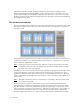
Reviewing the vault layout You must use a Linux partition editor, such as fdisk, parted, druid, or the HP Array Configuration Utility, to view the current configuration. (The HP Array Configuration Utility is available as part of HP SmartStart, but using HP SmartStart requires that you reboot VTS.) The following steps use parted to view the current partition layout: 1. Log in to the VTS server as the root user. 2.
3. Create partitions on the disk. If the disk partition is less than 2TB in size, complete these steps: a. Starting with the first recognized disk after the system disk, create the partition by entering the following command: fdisk /dev/cciss/c0d1 The fdisk command displays a : prompt. b. Print the current partition table by entering the following command: p c. Delete any partitions that you want to reconfigure by entering the following command: d d.
e. Create a primary partition at the beginning of the disk (4TB in this example): mkpart primary 0 4000G Or, you can create multiple partitions to consume all disk space: mkpart primary 0 50% mkpart primary 51% 100% f. Review the layout by entering the following command: print Here is an example of the output: Model: Compaq Smart Array (cpqarray) Disk /dev/cciss/c0d1: 2500GB Sector size (logical/physical): 512B/512B Partition Table: gpt Number 1 2 Start 17.
Adding vaults on external storage devices If an external storage device is connected to VTS, you can use it to configure additional vaults. Up to 100 vaults are supported per VTS server. Note If GFS is used in your VTS environment, see Maintaining GFS for VTS on page 157 for instructions to create vaults. To add a vault to VTS 1. If necessary, connect the external storage device to VTS. Make sure that the cable is plugged in and the link light is illuminated (for Fibre Channel) on the VTS server.
d. If the partition is not visible, enter the following command to scan the SCSI connections and detect new hardware: /usr/local/tape/bin/rescan-scsi-bus.sh -l -c -r -w Output similar to the following is displayed: 1 new device(s) found. 0 devices indicates that this is a pre-existing SAN. If you cannot see the partition after rescanning the SCSI connections, reboot the VTS server. 4. If the disk partition is less than 2TB in size, complete the following steps to configure the disk partition: a.
c. Create a primary partition at the beginning of the disk (3TB in this example): mkpart primary 0 3000G Or, you can create multiple partitions that consume all available disk space: mkpart primary 0 50% mkpart primary 51% 100% d. Quit parted. quit 6. Format the disk partition by entering the following command: mke2fs -j -L /VAULT01 /dev/sdc1 When specifying a vault name, use the following format: VAULTnn, where nn indicates a number. Repeat this command, incrementing nn for each new vault.
Renaming vaults You may need to rename a vault that is used by VTS. This example demonstrates how to rename /VAULT03 to /VAULT05. To rename a vault 1. Click Administration→System Tasks on the navigation pane and then click Stop TapeServer. 2. Log in to the server as root. 3. Review the existing vault layout and identify the device to rename.
Enabling Licensed Features Before you can use Virtual TapeServer (VTS), you must enable licensing. You can enable licensing for the following: • Managed capacity, which includes licensing for virtual tape libraries (VTLs) • Standalone virtual tape drives (VTDs) and compression, if included • Data Encryption Suite • Data Replication Suite, which is implemented as replicate jobs • 300Mb, 1Gb, 2.
3. Click Manage System Licenses. The following page is displayed: 4. Enter license keys as described in the help. To view the help, click the Help button at the top of the page. 5. If this is the first time you are entering license keys, you are prompted to accept the enduser license agreement. Read the agreement and click ACCEPT. If you do not accept the agreement, you cannot use the server. 6. Restart the TapeServer service. Click Administration→System Tasks on the navigation pane.
3. Click Manage System Licenses. The following page is displayed: 4. Configure licensing as described in the online help. To view help, click Help at the top of the page. 5. Restart the TapeServer service. Click Administration→System Tasks on the navigation pane. Then, click Stop TapeServer and then click Start TapeServer.
18 | Enabling Licensed Features
Configuring Ports After cabling the host server(s) and external devices to the VTS server, you must configure the ports to enable VTS to communicate properly with each device (target or initiator). If you attach an external tape drive or external disk array to the server after initial configuration, you must define the port as physical. Ports connected to host servers must be defined as virtual. Requires the View/Manage Configuration access right To configure ports 1.
20 | Configuring Ports
Creating and Managing VTLs and VTDs After Virtual TapeServer is deployed, you can create virtual tape libraries (VTLs). A VTL emulates the functionality of a tape library, which contains one or more tape drives, magazines that hold tape cartridges, a barcode reader to identify tape cartridges, and a media changer for loading and unloading tape cartridges.
A naming convention is used when the components of the VTL are created. The VTL name is specified by the user. All other names are automatically assigned by VTS.
3. Click Add Virtual Tape Library in the VIRTUAL TAPE LIBRARIES section of the page. The following is displayed: 4. Configure the VTL as described in the help. To view the help, click the Help button at the top of the page. The VTDs are then mounted. The VTDs are listed in the VIRTUAL TAPE DRIVES section of the Configure Virtual Devices page. Be sure that no errors are displayed on the web interface, and if problems arise, verify vault permissions.
To view the contents of VTLs On the navigation pane, click Administration→Virtual Tapes. Note No virtual tapes are displayed until you select an option from the Show Cartridges In drop-down list. You can use the drop-down lists at the top of the page to control the view: • To view virtual tapes on the shelf only, select Shelf from the Show Cartridges In dropdown list. • To view virtual tapes in a VTL, select the VTL name from the Show Cartridges In dropdown list.
Presented to Host? Property Description Serial number The serial number or other string describing the VTD. Only alphanumeric characters should be used. Yes The port ID, target ID, LUN, and initiator ID (not shown) are collectively referred to as the PTLI. The PTLI enables the host server to precisely identify the VTD; it provides an exact address of the VTD on the port. Remember that the host is connected to VTS by a single cable.
3. Click Configuration→Virtual Devices on the navigation pane. The Configure Virtual Devices page is displayed: 4. Click Add Virtual Tape Drive in the VIRTUAL TAPE DRIVES section of the Configure Virtual Devices page. The following is displayed: 5. Configure the VTD as described in the help. To view the help, click the Help button at the top of the page. You can now create virtual tapes for use with VTDs. Back up the database after modifying the VTS configuration.
To view virtual tapes in VTDs Click Configuration→Tapes and Pools on the navigation pane. All VTD and virtual tape procedures are documented in the online help. To view the help, click the Help button at the top of the Manage Virtual Tapes page. Configuring the NonStop BladeSystem Cluster I/O Module If the NonStop BladeSystem is used as the host server and the Cluster I/O Module (CLIM) will be used, you must configure the virtual tape drives on the NonStop. Complete the following steps to do so: 1.
Validating access to VTDs from the NonStop server To validate that the NonStop server can back up to configured VTDs in VTS, you must configure the NonStop server to add the VTD. Then, you can start the virtual tape drive from the NonStop server. Issue the following command on Integrity series servers to configure the virtual tape drive: SCF ADD TAPE $VTD, SENDTO STORAGE, LOCATION (x,y,z), LUN #, SAC #, PORTNAME WWN#, COMPRESSION OFF where $VTD The virtual tape drive name, such as $TAPE00.
This command should return messages similar to the following if successful: SCF - T9082G02 - (06JAN06) (31OCT05) - 01/19/2007 08:42:11 System \DEV3 (C) 1986 Tandem (C) 2006 Hewlett Packard Development Company, L.P. Total Errors = 0 Total Warnings = 0 If unsuccessful, messages similar to the following are displayed: SCF - T9082G02 - (06JAN06) (31OCT05) - 01/19/2007 09:09:06 System \DEV3 (C) 1986 Tandem (C) 2006 Hewlett Packard Development Company, L.P. STORAGE E00002 START TAPE \DEV3.
30 | Creating and Managing VTLs and VTDs
Enabling and Performing Tape-to-tape Exports You can export a virtual tape to physical tape using a tape-to-tape export job. This provides a one-to-one mapping of virtual to physical tape. You can export to a drive in a library or a standalone drive. When creating the tape-to-tape export job, you can choose whether the data remains in virtual tape format or host format.
• enable VTS to export virtual tapes that were encrypted by the Data Encryption feature of VTS if all drives in the target physical library support encryption (LTO-4 and LTO-5 drives only) • disable an external tape device, making the device unavailable during job creation Requires the System Maintenance Functions and View/Manage Configuration access rights To configure a physical drive or library for tape-to-tape exports 1. Click Configuration→System on the navigation pane of the VTS web interface. 2.
Requires the Virtual Tape Import and Export, Vault Access, and Access to all Vaults access rights To export a virtual tape or pool 1. Click Administration→Virtual Tapes on the navigation pane. 2. Select All, Shelf, or a VTL name from the Show Cartridges In drop-down list. 3. Choose one or more virtual tapes to export. (In a later step, you can also choose virtual tapes in VTLs or pools.
34 | Enabling and Performing Tape-to-tape Exports
Enabling and Performing Stacked Exports Through integration with a backup management application server, you can read and write files to and from Virtual TapeServer (VTS). You can then create stacked export jobs on VTS to export, or “migrate”, virtual tapes to physical tapes using an attached external tape device. Note Stacked export jobs are available if a capacity license is enabled on the server. Stacked exports allow for better use of the disk space on the storage array.
interface. This restores the virtual tape to VTS so that a host server can then use the tape. Refer to the help for importing instructions. Configuring the physical drive or library After attaching a physical drive or library to VTS as described in the Quick Start Guide, you can export virtual tapes to physical tapes. Before creating stacked export jobs, you can assign a user-friendly name to a drive or library, and you can dedicate a drive or library for stacked exports.
Setting the backup management application password You can configure a system account for use by backup management applications (for stacked exports). To configure a system user account 1. Click Security→Passwords on the navigation pane of the VTS web interface. A page similar to the following is displayed: 2. Select hsm from the drop-down list. 3. Type the username and password that is required to log in to the backup management application and then click Update.
3. Choose one or more virtual tapes to export. (In a later step, you can also choose virtual tapes in VTLs or pools.) 4. Select Stacked Export from the Actions drop-down list (above the table, on the right side of the page). The Stacked Export pop-up dialog is displayed. 5. Select the Create New Job option. 6. Specify the job options as described in the help. To view the help, click the Help button at the top of the Manage Virtual Tapes page. 7.
Enabling and Configuring Data Replication Data Replication enables you to back up data to remote Virtual TapeServer (VTS) servers. This feature is implemented as • Replicate jobs, for redundancy or disaster recovery purposes • Remote export jobs, for high availability and role swapping purposes Use replicate jobs to replicate data as part of your disaster recovery solution or to enable multiple Virtual TapeServer servers to back up virtual tapes to a single remote server.
At a glance, here is an overview of the steps to enable, configure, and use replicate jobs: 1. Configure data partitions on the remote (target) servers. 2. Enable Data Replication licensing using the VTS web interface as described in Enabling Licensed Features on page 15. 3. Configure source and target settings using the web interface. 4. Replicate data to remote servers by creating and running replicate jobs.
• Use data partitions instead of vaults. • Use /DATAxx instead of /VAULTxx, and use the chown and chmod commands to change the ownership and file system mode of the partitions. • Data partitions cannot be shared across GFS file systems. Enabling Data Replication licensing Before you can use the Data Replication feature, you must enable licensing. Requires Administration group membership To enter a license key 1. Click Configuration→System on the navigation pane. 2. Click Manage System Licenses.
Requires Administration group membership To add a target server Complete these steps using the web interface on the source server: 1. Click Configuration→System on the navigation pane. 2. Click Edit System Settings. 3. Click Replication to expand this area of the page. 4. Click the Add Target Host button. The following is displayed: 5. Specify target settings as described in the help. To view the help, click the Help button at the top of the page.
3. Click Replication to expand this area of the page. The following is displayed: 4. Authorize, enable, and specify settings as described in the help. To view the help, click the Help button at the top of the page. To complete the connection and enable the target server After the target authorizes and enables this source, complete these steps using the source server's web interface: 1. Click Configuration→System on the navigation pane. 2. Click Edit System Settings. 3.
Replicating data to remote servers To replicate data to remote servers, you must create and run a replicate job. Note Partial procedures are provided below. Be sure to display the online help for full details; click Help at the top of the Manage Virtual Tapes page. Requires the Virtual Tape Import and Export, Vault Access, and Access to all Vaults access rights To create and run a replicate job 1. Click Administration→Virtual Tapes on the navigation pane. 2.
Enabling and Configuring Role Swapping To enable “role swapping” of primary and secondary Virtual TapeServer (VTS) servers in your environment, or to ensure high availability of data across sites, you can license and use the Data Replication feature. Data Replication enables you to back up data to remote VTS servers.
• Ownership of virtual tapes is not stored, so there is no way to inform the administrator of either system of the originator of the virtual tape. • Remote export jobs push virtual tapes from one system to another. It is your responsibility to disable the remote export jobs on current primary server (at the production site) and enable them on the current secondary server when swapping roles. If you do not disable all jobs on the production site, data may be overwritten.
d. Remove virtual tapes from the newly created VTLs, if VTLs were created. These virtual tapes are created automatically but cannot be used to store data that is exported by the remote export jobs. Refer to the online help for instructions. e. Recreate and schedule all of Server A’s jobs on Server B, including the remote export jobs (whose target should be Server A). Be sure to disable these jobs; they should not run until after the roles of the servers have been swapped.
Configuring network settings You must configure network settings for all VTS locations. To configure the primary (local) system, you must attach a monitor, keyboard, and mouse to the VTS server. To configure secondary (remote) systems, you must use a remote-access application to access those systems, or perform the steps at each site. The IP address, which will differ for each VTS server, must be configured at the primary and secondary sites.
3. Test connectivity by pinging the network connections. At the prompt, enter ping hostname. For example, to ping Server B, enter ping server_b. Output similar to the following is displayed: 64 64 64 64 bytes bytes bytes bytes from from from from server_b server_b server_b server_b (10.10.2.145): (10.10.2.145): (10.10.2.145): (10.10.2.145): icmp_seq=0 icmp_seq=1 icmp_seq=2 icmp_seq=3 ttl=64 ttl=64 ttl=64 ttl=64 time=0.053 time=0.053 time=0.053 time=0.
c. At the command prompt, enter ssh user@server uptime. For example, on Server B, enter ssh bill@server_b uptime. The first time you enter an ssh command, a message similar to the following is displayed: The authenticity of host 'server_name (IP_addr)' can't be established. RSA key fingerprint is 5f:10:3c:47:78:8f:e3:28:9d:ab:6b:34:ed:d1:e4:08. Are you sure you want to continue connecting (yes/no)? Enter yes. d. Repeat these steps on each VTS server.
Configuring settings for remote export jobs Note A default configuration file is defined for each VTS server. To override the default settings, you must define settings as described below. Requires the Edit Configuration File access right To modify the configuration file to configure remote export jobs 1. Enable Data Replication licensing as described in Enabling Licensed Features on page 15. 2. On the primary (originating) server, complete these steps: a.
3. On the secondary (target) servers, add the rep_source_hosts parameter to the configuration file, as follows: a. Click Configuration→System on the navigation pane. b. Click Edit Configuration File. c. Add the rep_source_hosts parameter to the bottom of the file that is displayed. This parameter specifies a list of authorized primary (originating) hosts. The list of target locations cannot be generated unless the originating source is listed. This parameter is required. Example vts.
Configuring EMS Communication To automate the process of mounting and dismounting virtual tapes, you must configure the Event Management System (EMS) on the Virtual TapeServer (VTS) server. The EMS service for NonStop servers starts the EMS distributor on the NonStop server by issuing a Tandem Advanced Command Language (TACL) command. The distributor notifies the VTS EMS service when an EMS message is posted on the NonStop server.
c. Enable EMS and configure the settings, as described in the help. To view the help, click the Help button at the top of the page. 4. Set the username and password for each EMS host: a. Click Security→Passwords on the navigation pane. The following page is displayed: b. Configure a password for each EMS host defined in the configuration file. Click Help for complete instructions. 5. If you configured EMS to use SSH, you must log in to each host server to verify and accept the fingerprint.
d. Enter yes to accept the fingerprint. If a mismatch occurs after accepting the fingerprint, you can edit the /home/bill/.ssh/ known_hosts file to remove lines for host server whose key has changed. Then, after the obsolete key has been removed, repeat this step to accept the new key. 6. Click RESTART on the Virtual Media - Mounts and Locks page to restart the EMS service. Or, click Start EMS Service on the Manage System Tasks page.
56 | Configuring EMS Communication
Enabling and Configuring Data Encryption Data Encryption is an optional Virtual TapeServer (VTS) licensed feature that enables VTS to encrypt data that is stored on virtual tape. Here is how Data Encryption affects tape operations: • When an encrypted tape is mounted, the data that is written to the tape is encrypted. You can also instruct VTS to encrypt data that is already stored on a virtual tape if the tape is not encrypted.
key in the database ensures that the key will not be compromised and that it resides in a central, secure location with all other keys. The key database is backed up on the key server and on at least one other remote server to ensure that a backup of the keys is always available in case the key server is damaged or destroyed. The backup must complete successfully on the localhost and backup host before the keys are available for use by VTS. This ensures that keys are backed up before data is encrypted.
Multi-server considerations Keep the following in mind when configuring and using Data Encryption in an environment with multiple VTS servers, such as if GFS or Data Replication is configured: • Server configuration When configuring key servers and backup hosts for Data Encryption, it is highly recommended that you configure only one key generator for the environment. You must also configure at least one other server in the environment that can serve as the backup host for the key database.
Enabling Data Encryption licensing Before you can use the Data Encryption feature, you must enable licensing. Requires Administration group membership To enter a license key 1. Click Configuration→System on the navigation pane. 2. Click Manage System Licenses. A page similar to the following is displayed: 3. Enter the Data Encryption license key as described in the help. To view the help, click the Help button at the top of the page.
If three VTS servers — A, B, and C — are installed in your environment, you must perform these tasks to fully enable and configure Data Encryption: 1. Determine which server will be responsible for generating keys. For this example, server A will be the “key generator”. 2. Add server A as a key generator on servers B and C. 3. On servers B and C, remove the localhost key server. (The localhost entry is configured as a key generator.) 4.
Prerequisites for configuration Before you begin, ensure the connection between the host and VTS servers is secure. Then, ensure that the connection between the VTS server and the physical drive or library is secure if you want to export encrypted virtual tapes. You may also want to gather the following information to expedite the configuration process: • Username and password of a VTS user account that belongs to the Administration group.
3. Click ADD NEW SERVER in the KEY SERVERS section of the page. The following is displayed: 4. Specify key server settings as described in the help. To view the help, click the Help button at the top of the page. After you add a key generator and a key database backup host (other than localhost), allow five minutes for the key generator to create the first set of keys and key IDs. Key IDs may not be available until after this initial time period.
3. Click ADD NEW HOST in the KEY DATABASE BACKUP/RESTORE HOSTS section of the page. The following is displayed: 4. Specify host settings as described in the help. To view the help, click the Help button at the top of the page.
Creating and Managing Virtual Media VTS organizes data in vaults, which are defined for you. Vaults contain pools, and pools contain virtual tapes. You can create, modify, and delete pools.
Requires the Virtual Tape Pool Maintenance, Vault Access, and Access to all Vaults access rights To create a pool 1. Click Configuration→Tapes and Pools on the navigation pane. The Configure Tapes and Pools page is displayed. 2. Select pool maintenance from the window drop-down list at the top of the Configure Tapes and Pools page. The Virtual Media - Pool Maintenance page is displayed. 3. Specify pool settings as described in the help.
Creating virtual tapes You must create a virtual tape (for use with standalone VTDs) before the host server can mount and write data to it. When you create a virtual tape, a file is created on the VTS server’s disk.
Labeling virtual tapes on the host server After creating pools and virtual tapes, you must label the virtual tapes on the host server. Refer to the host server documentation for complete labeling instructions. To label virtual tapes 1. Configure VTS to automatically load and unload virtual tapes as they are used, from the first to the last virtual tape in the pool. See the “Modifying a pool” help topic and select the Autoloading checkbox. 2.
Encrypting a single virtual tape You can encrypt a single virtual tape after you create it. Requires Administration group membership To encrypt a virtual tape 1. Click Configuration→Tapes and Pools on the navigation pane. 2. Log in using an account that is a member of the Administration group. Click the Log In button at the top of the page and enter a username and password. 3. Click the virtual tape you want to encrypt. 4. Click the Encrypt button above the table.
Mounting virtual tapes You can manually mount a virtual tape in a standalone VTD. (You can automate mounting using the Event Management System; see Configuring EMS Communication on page 53.) Then, to backup to the mounted virtual tape, use the backup software you normally use to perform a backup to the mounted VTD. When you mount a virtual tape, its modification date is not updated; the ctime (inode change time) is updated.
3. Select the virtual tape to mount. In the following snapshot, the DF0000 virtual tape will be mounted on the VF40500 host device: 4. Click Mount. The following dialog box is displayed. Note If the Mount button is not displayed, see You can set a number of parameters in the VTS configuration file to specify the following: on page 115 for information about displaying this button.
6. After the backup begins, you can monitor the progress from the Configure Tapes and Pools page. In the kb/sec and size(MB) columns, you can see the megabytes that have been backed up and the backup rate: After the backup completes, you can verify that the size of the virtual tape has changed. You can also monitor progress from the System Status page, which shows the current transfer rate (if enabled). When the backup is finished, VTS unloads the virtual tape.
Requires the Virtual Tape Mounts and Locks access right To view mounts 1. Click Configuration→Tapes and Pools on the navigation pane. 2. Select mounts and locks from the window menu at the top of the Configure Tapes and Pools page. The top of the page shows the recent mount requests. Only mount requests that can be handled by the server are displayed. You can also restart the EMS messaging service from this page by clicking the RESTART button.
that of the host that originally transferred the data to VTS, where it was stored as a virtual tape. If you export a pool, you can only import the tape(s) back into VTS. Also, when exporting a pool, only those virtual tapes that contain data are exported. You can also use migration to automatically export tapes, through the use of VTSPolicy. If migration is not enabled and configured, contact HP Global NonStop Solution Center (GNSC) for support.
3. Click Import/Export. Or, if Data Encryption is enabled and the tape is encrypted, click Import/Decrypt&Export. The Virtual Media - Import/Export page is displayed. If one or more physical tape drives are connected to VTS, they are detected automatically. (If a physical tape drive is not listed, such as if it was connected after VTS was booted, you may need to rescan the SCSI controllers. See Common issues on page 127 for more information.
6 Could not rewind tape after copy 7 Could not issue SCSI write command 8 SCSI write command failed Migrating a virtual tape to physical tape using the web interface You can export a pool, which exports all virtual tapes in the pool, or you can export a single virtual tape. This is also referred to as “migration”. The virtual tape or pool is migrated according to the hsm_ parameters in the VTS configuration file.
Automatically migrating virtual tapes to physical tapes using VTSPolicy After BMA integration is configured, which enables a backup management application server to read and write files to and from VTS, you can use VTSPolicy to initiate migration by having the NonStop server send an EMS message to the VTS server. The VTS server then uses the VTSPolicy command to invoke the backup management application to complete the desired operation. VTS waits for the return code from the backup management application.
erase Enables VTS to erase the virtual tape after migration is completed successfully. Set this keyword to YES or NO. This keyword is not required and defaults to NO. delete Enables VTS to delete the virtual tape after migration is completed successfully. Set this keyword to YES or NO. This keyword is not required and defaults to NO. locked Enables VTS to lock all specified virtual tapes. Set this keyword to YES or LOCK. This keyword is not required and defaults to LOCK.
To configure the VTSPolicy command for Syncsort Backup Express Here is the syntax of the VTSPolicy command for use with Backup Express. Note that all parameters specified for the command are case-sensitive. VTSPolicy BEX 'backup_type /VAULTxx/pool/cartridge [keyword=value ...]' where backup_type. Specifies the type of backup. You can specify one of the following values: backup_base or backup_difr. /VAULTxx/pool/cartridge Specifies the pool and cartridge on which to operate.
For example, to migrate the virtual tape named CART01 on the VTS1 server and erase the selected files from VTS, issue the following command: VTSPolicy NBP '/VAULT01/POOLA/CART01 s=VTS1 erase=YES' To configure the VTSPolicy command for CommVault Galaxy Here is the syntax of the VTSPolicy command for use with CommVault Galaxy. Note that all parameters specified for the command are case-sensitive.
Specify how the message will be displayed in an EMS viewer, such as ViewPoint. In this example, inverse text is used until the event is acknowledged but the event is listed in normal text: #SET action -1 #SET emphasis -1 Issue the VTSPolicy command; see Automatically migrating virtual tapes to physical tapes using VTSPolicy on page 77 for an explanation of the parameters.
Otherwise, if a VTD license is enabled, you can import a physical tape to a virtual tape using the Import/Export page of the web interface. The import feature was designed for occasional low-volume use and requires that a standalone tape drive or simple cartridge autoloader is connected to VTS. You must ensure that the tape drive is available and that appropriate tape media is installed before beginning an import operation. Refer to the online help for procedures.
To erase or delete a virtual tape from the Configure Tapes and Pools page 1. Unmount the virtual tape first, if it is mounted. 2. Click Configuration→Tapes and Pools on the navigation pane. The Configure Tapes and Pools page is displayed. 3. Select a virtual tape in the cartridge column. You may need to expand a pool to see the list of virtual tapes. 4. Click Erase to erase the contents or click Delete to delete the entire tape.
To erase or delete a virtual tape from the Cartridge Maintenance page 1. Click Configuration→Tapes and Pools on the navigation pane. 2. Select cartridge maintenance from the window drop-down list at the top of the Configure Tapes and Pools page. The Virtual Media - Cartridge Maintenance page is displayed. 3. Select a pool where the virtual tape(s) reside from the Pool drop-down list. 4. If erasing or deleting a single virtual tape, enter the name of the virtual tape in the Cartridge field.
Automatically erasing a virtual tape using Scan/Cleanup After you enable and configure Scan/Cleanup as described in Enabling and Configuring Scan/ Cleanup on page 91, you can display the web interface for this feature by clicking Configuration→Tapes and Pools on the navigation pane. Then, select scan/cleanup from the window drop-down list. The Scan/Cleanup page is displayed.
Size Displays the size of the virtual tape (in bytes). This reflects the size of the tape data; it excludes the size of the metadata (up to 27MB). Erase Indicates whether the virtual tape is selected for erasure or not. This column also provides an explanation of the business rule that is controlling the erasure status. In the following example, virtual tape X00001 was erased on 13Feb05 15:43, last written on 17Feb05 14:49, will be retained for two weeks, and has never been migrated.
Also, if the meta_control_panel parameter is set to YES, the Meta Data Control Panel is displayed at the bottom of the page. This control panel enables you to read and write metadata. Metadata is stored with the virtual tape but is not part of the data itself.
To delete the virtual tape named GB0002, and to indicate that the vts-prod2 server should process this policy request, issue this command: VTSPolicy Delete - GB0002 s=vts-prod2 You can issue a simple FUP call to copy the contents of a text file to the $0 process. Create a text file on the NonStop server that contains the VTSPolicy command. Then, from Batchcom or within an existing backup script, run the following command: FUP COPY filename, $0 This sends the contents of the file to the EMS collector.
#PUSH evt_num action emphasis evt_text text_len #SET evt_num number #SET action -1 #SET emphasis -1 #SET evt_text VTSPolicy Erase|Delete - virt_tape...
To remove a lock 1. Click Configuration→Tapes and Pools on the navigation pane. 2. Select mounts and locks from the window menu at the top of the Configure Tapes and Pools page. 3. Select the pool or virtual tape to unlock at the bottom of the page. 4. Click REMOVE LOCK.
Enabling and Configuring Scan/Cleanup Scan/Cleanup is a Virtual TapeServer (VTS) feature that is designed to help you maintain VTS. It scans pools and virtual tapes to identify virtual tapes that are past their retention period. Scan/Cleanup can erase old virtual tapes to recover disk space. You can also schedule virtual tape erasures when the overall disk space falls below a specified threshold. Scan/ Cleanup can be used to erase tapes after they are exported to physical tape using stacked export jobs.
• You can force an erasure or block an erasure by using the checkboxes on the Scan/Cleanup page. However, when an erase process completes (either auto-erase or erase-now), these overrides are removed. • When Scan/Cleanup erases a virtual tape, the header information (metadata) remains stored on VTS. • Scan/Cleanup does not affect a virtual tape's encryption setting. This chapter describes how to enable and configure Scan/Cleanup.
Parameter Description Values cleanup_autoerase Enables Scan/Cleanup and controls the automated erase process. When set to NO, Scan/Cleanup is disabled and the Scan/ Cleanup page displays the erasure cleaning status of each virtual tape but no virtual tapes are erased without further configuration. YES or NO Default value: NO If you want to automate virtual tape erasures, set this parameter to YES and set the cleanup_scan_at and cleanup_interval parameters.
Parameter Description Values cleanup_show_erase_ control_files Displays Scan/Cleanup files that are used to implement the Scan/Cleanup erasure process. This is typically set to NO and may be enabled to help diagnose a system problem, if indicated. YES or NO Default value: NO cleanup_minimum_size_ GB and cleanup_minimum_size_ MB Define which files to ignore based on size by using either cleanup_minimum_size_MB or cleanup_minimum_size_GB.
Parameter Description Values cleanup_show_size_ column Shows or hides the Size column in the Status Table. YES or NO Default value: NO meta_control_panel Shows or hides the Meta Data Control Panel, which enables you to read and write metadata on the virtual tape. Set this parameter only if diagnosing problems or instructed to do so by Support.
96 | Enabling and Configuring Scan/Cleanup
Configuring User Accounts This chapter describes how to manage and use the operating system and web interface accounts on the VTS server. Managing operating system accounts By default, the following user accounts are provided for the VTS operating system (Linux): • root • bill • vtsa The first time you log in to the VTS operating system using one of these usernames, you are prompted to change the password.
• Through “sudo”, can issue the following commands: • /sbin/tune2fs -l /* (runs as root) • /bin/cat • /usr/bin/passwd • /usr/local/tape/bin/ getVTS_dbginfo (runs as root) • /sbin/chkconfig • /bin/ping • /bin/bash/usr/local/tape/bin/ • /usr/bin/clear getVTS_dbginfo (runs as root) • /bin/ps • /usr/bin/updatedb (runs as root) • /usr/bin/crontab • /sbin/reboot (runs as root) • /sbin/fdisk -[vl] (runs as root) • /bin/date • /usr/bin/rsh • /sbin/fdisk -[sl] /* (runs as root) • /bin/df • /usr/bin/
Adding accounts You can create additional accounts in the vtsmaint group, and the new user will have the same privileges as the vtsa user. To create an account 1. Log in to the VTS server. 2. Become the root user: su 3. Enter the following command to create the user account: useradd -n username 4.
You can also use the following commands: chage -l user_acct Lists expiration information chage -M -1 user_acct Removes expiration from an account Restricting access to bill The bill account has the same access rights as the root account. You can restrict access of the bill account, thereby forcing users to use vtsa and denying access to functions that may present security vulnerabilities. To restrict access to bill 1. Log in to the VTS server as root. 2.
If you have system administrator privileges, you can configure access control to grant or limit access to specific VTS functions. Each login ID belongs to a group and each group has a unique set of privileges. Note VTS provides a user that has administrator privileges. You can log in as admin if no other administrative user is created on the system. The default password for this user is virtual.
Below are closed system defaults: • • Users — The following users are defined. Username Group admin Administration operator Operations tapelabs Supervisor Groups — The following rights are assigned to the groups: Note The rights are organized in categories. If you grant access to a category, all rights in the subcategories are granted by default, though you can remove individual rights in the subcategories.
Rights Administration Group View log files X View/Manage Configuration X Virtual Tape Operations X Operations Group Supervisor Group X X X Scan and Cleanup Control Panel X X Virtual Tape Cartridge Maintenance X X Delete Cartridges X X Virtual Tape Import and Export X X Virtual Tape Instant DR X X Virtual Tape Mounts and Locks X X Virtual Tape Pool Maintenance X X Erase Cartridges X X HSM Migration X X Mount Cartridges X X Unmount Cartridges X X View System Status
c. In the add group field, type a name for the group. d. Click APPLY. 5. Add the user to the group: a. Deselect the new user in the Users drop-down list and select it again to enable the CHANGE GROUP button. b. Click CHANGE GROUP. c. Select the group from the in Group drop-down list. d. Click APPLY. 6. Assign rights to the group: a. Expand + to expand Rights. b. Select the 1.3 Virtual Tape Operations access right only. c. Click APPLY.
3. Click + to expand Users and Groups. 4. Click ADD next to Users. The name and password fields are displayed. 5. Type a username in the name field. Usernames cannot contain spaces and cannot duplicate existing usernames, group names, or reserved names. Also, they must be alphanumeric, though they can include an _ (underscore) character. 6. Type a password in the password field.
7. Click APPLY. The user is added and additional buttons are displayed. 8. To assign the user to a group, click CHANGE GROUP. The Group drop-down list is displayed. Note The user cannot perform functions until you assign the user to a group. 9. Select a group from the drop-down list and click APPLY.
Changing any user’s password It is highly recommended that you change the passwords of the default users. Requires the System Access Controls access right to change any user’s password To change a user’s password 1. Click Security→Access Control on the navigation pane. 2. If prompted, log in. After logging in, the Manage Access Control page is displayed. 3. Click + to expand Users and Groups.
4. Select the user from the Users drop-down list. 5. Click SET PASSWORD. The Password field is displayed. 6. Type a new password in the field. 7. Click APPLY. Configuring groups Groups define the access rights that are assigned to users. Three groups are provided: • Administration • Operations • Supervisor For a list of the default rights assigned to these groups, see page 102. You can modify the access rights that are assigned to these groups.
3. Click + to expand Rights. 4. To modify access rights assigned to the Administration group, select the checkbox next to each access right in the Administration column. Note The rights are organized in categories. If you grant access to a category, all rights in the subcategories are granted by default, though you can remove individual rights in the subcategories.
Right Description Block and Unblock TapeServer Displays the Block/Unblock TapeServer Startup link on Manage System Tasks page, which enables the user to block and unblock VTS functions Database Download Enables the user to create a system restore image from the Manage System Updates page Database Upload Enables the user to restore a system restore image from the Manage System Updates page Edit Configuration File Enables the user to edit the VTS configuration file from the Manage System Configuratio
Right Virtual Tape Cartridge Maintenance Delete Cartridges Description Grants access to the Virtual Media - Cartridge Maintenance page Enables the user to delete virtual tapes from the Virtual Media - Operation and Virtual Media - Cartridge Maintenance pages Virtual Tape Import and Export Grants access to the Virtual Media - Import/ Export page Virtual Tape Instant DR Grants access to the Virtual Media - Instant DR page Virtual Tape Mounts and Locks Grants access to the Virtual Media - Mounts and Loc
Saving and restoring custom defaults After configuring users and group rights, you can save all settings as a custom configuration. Later, you can restore these settings by simply clicking the Restore CUSTOM Defaults button in the Defaults and Undo section of the page. This button becomes available after you save a custom configuration. These procedures require the System Access Controls access right To save custom default settings 1. Click the Save as CUSTOM button above the access rights table. 2.
To restore the custom default settings Click the Restore CUSTOM Defaults button to restore the custom configuration and discard changes made since the custom defaults were last saved.
114 | Configuring User Accounts
Configuring Web Interface Preferences This chapter describes how to configure web interface preferences by setting parameters in the configuration file and how to set the refresh rate of the System Status page. You can set a number of parameters in the VTS configuration file to specify the following: • Whether and how often to display status messages at the top of the page. • Whether and when to display a notification regarding low vault space.
Parameter Description Values opwin_ImportExport Displays the Import/Export button on the Configure Tapes and Pools page. YES or NO Default value: YES opwin_Migrate Displays the Migrate button on the Configure Tapes and Pools page. Note that the hsm_enable parameter must also be set to YES to display the button. YES or NO Default value: YES opwin_AllowAutoRefresh Whether to allow auto-refresh on the Configure Tapes and Pools page. This also displays the kb/sec column on the page.
Parameter Description Values lowspace_notify Enables notification on low vault space. If EMS is enabled, a message is also sent to the NonStop host server (the ems_hsm_backup_notification or ems_notification_enable parameter must also be set to YES). YES or NO Default value: YES lowspace_notify_keep Specifies whether to continue to display the low vault space notification until it is no longer valid.
118 | Configuring Web Interface Preferences
Managing the VTS Server This chapter describes several tasks that are performed from time-to-time as needed. For more information about system tasks, refer to the online help. Backing up the VTS server It is recommended that you back up the VTS server before and after any major operation, such as an upgrade.
3. If Data Encryption is enabled, back up the most current backup of the key database by completing these steps: a. Log in to the VTS server. b. Use the su command to change to the bill user: su - bill c. Determine the location of the most recent backup file by entering the following command: psql -d database -c "SELECT last_local_backup FROM ks_backup_config" Here is an example of the output from this command: last_local_backup ------------------------------------------/VAULT00/.ks_backups/LocalKSBackup.
Configuring system settings You can configure the following settings for the VTS server: • Session timeouts, to allow inactive browser and command line sessions to time out • SMTP settings, to define the email host and port that will use to send email notifications • Notification settings, to define email addresses that will notifications about disk and capacity usage To configure system settings 1. Click Configuration→System on the navigation pane. 2. Click Edit System Settings.
To power down 1. Stop tape services on the NonStop server by entering the SCF STOP $VTAPE command, where VTAPE is the name of the tape device. Here is an example of the output: SCF - T9082H01 - (04DEC06) (15NOV06) - 10/02/2008 11:55:37 System \DEV5 (C) 1986 Tandem (C) 2006 Hewlett Packard Development Company, L.P.
To review fsck status 1. Click Administration→System Tasks on the navigation pane of the VTS web interface. 2. Click View File System Check Information. The FSCK Information page is displayed: For more information, see the online help. To view help, click the Help button at the top of the page. Monitoring files and directories The following files and directories should be monitored. Remove old data as needed.
The system facility, which is called logrotate, is used to rotate log files on a daily basis. The configuration files for logrotate are located in /etc/logrotate.d. You can tune the settings in this file to rotate and overwrite files as needed. Several scripts are available that clean up after files that were created and abandoned due to system or application errors. These include the following: • rmoldpipes • rmoldbylist • rmoldsync • rmoldfilelist.
Troubleshooting This chapter provides information to assist you in addressing problems you may encounter while installing and using VTS.
Virtual Network Computing remote control software VNC software enables you to remotely access the console of a UNIX server. VNC must be configured on the host server before you can use it from a client. You can download VNC from http://www.vnc.com/. HP health monitoring utilities The VTS server provides the following: • HP Systems Insight Manager (SIM_6.2_575369_004.bin) • HP Insight Diagnostics (hpdiags-8.7.0-26.linux.x86_64.rpm) • HP System Health Application and Command Line Utilities (hp-health-8.
Note that if you are using a serial connection over the physical serial port (connected through /dev/ttyS0), use the following connection settings: • Speed: 115200 bps • Data Bits: 8 • Parity: None • Stop bits: 1 After iLO or Lights-Out 100 is configured, you can enable iLO or Lights-Out 100 access on the system boot menu by running /usr/local/tape/bin/grub-serial.bash as root and then rebooting the system.
If the drives are operational but errors are encountered while accessing the data, check the media class, or density, setting for that cartridge using the DSPTAP command. The currently recommended media classes supported by AS/400 with VTS are the following: • 3580-TD1 • 3580-TD3 • 3580-TD4 VTS server module You can troubleshoot various areas of the VTS server module.
File system Verify the following: • Has anything changed? • Is performance slow? • Is GFS running on the system? • Is the problem occurring for a particular vault or all vaults? Is the problematic vault on internal or external disk storage? • What is the result of the last vault check on the external storage? You can check for FSCK messages in the system log and the result of the last vault check.
Web interface If the web interface stops responding, verify the following: • Access the interface from a different workstation. • Ping the address. • Check the Ethernet cable. • Check Ethernet connectivity and activity LEDs. The Apache web server is responsible for running the VTS web interface. To verify that Apache is running: /etc/init.d/httpd status A message similar to the following should be displayed: httpd (pid 25380 25015 25014 25013 25012 25011) is running...
Event Management System (EMS) Verify the following: • Has the EMS logon expired? • Is there network connectivity between VTS and the NonStop server? • Was the VTS operating system or the EMS template upgraded? • Is VTS up-to-date with the latest product enhancement code? • Is there a typographical error in the VTS configuration file? You can check the EMS log file for the last timestamp of messages.
• Check that the tape is in the drive. • Check the media write-protection. If you cannot access a virtual tape because it is locked, perform the following: • Check MEDIACOM for label in use. • Check other VTS systems for remotely mounted virtual tapes. • Reboot VTS to clear all local file locks. If an autoloading pool did not recycle, verify that Autoloading or Recycle is selected on the Pool Maintenance page.
• Exporting an encrypted tape: A message similar to the following is displayed on the web interface: Thu 2008-01-17 09:49:31: SHARE:SH0000 rc=3 • Export data transfer failed, Erasing all virtual tapes in a pool on the Cartridge Maintenance page: A message similar to the following is displayed on the web interface: Erased 1 cartridge; Erasure of cartridge SH0002 in pool SHARE failed! • Setting the virtual tape size on the Pool Maintenance page: A message similar to the following is displayed on the web
Log format Each entry in the event log follows the same format, as shown in the following example: 2006-08-28 16:25:18|WARNING|440002|5900-E| 127.0.0.1|Tapeserver01|administrator||Access Control RESTORE OPEN defaults have been restored Messages are up to 255 characters in length; each message field has a character limit. The attributes that have a variable length are automatically compressed to the available space.
Message severity The severity attribute indicates the potential impact of the event or condition that the message reports. Note Though you can change the debug level on the Set Debug Level page, the debug level is reset to Error every time VTS is restarted. The following table lists the severity levels for log messages, starting from the lowest level of impact to the highest. Severity ID Severity Level Description 2 Info A normal operation.
ID Subsystem 53 Virtual tapes 61 Access Control defaults 62 Access Control users 63 Access Control groups 64 Access Control rights 65 Secure password management 71 Erase by list 72 Delete by list 81 Crumb 91 System status Message text The following tables list the message IDs and corresponding message text that are generated for events in the system event message log.
Severity ID Subsystem ID Event ID Subsystem Message text 2 20 005 EMS unmount ems telnet ems dismount of TAPE by HOST 4 20 006 EMS cancel mount ems telnet cancel mount of TAPE 6 20 007 EMS cancel mount ems telnet cancel mount of TAPE failed 8 20 007 EMS Mount ems telnet mount of TAPE failed: Tape missing 4 20 008 EMS Mount Read-Write ems telnet ems mount of TAPE by HOST as read-write 8 20 008 EMS Mount ems queue cancel TAPE for HOST of type TYPE failed 2 20 010 EMS Poli
Severity ID Subsystem ID Event ID 2 20 8 Subsystem Message text 041 EMS Policy BEX ems telnet BEX completes, rc=0 20 042 EMS Policy BEX ems telnet BEX completes, rc=RC 2 20 050 EMS Policy TSM ems telnet TSM POLICY 2 20 051 EMS Policy TSM ems telnet TSM2 completes, rc=0 8 20 052 EMS Policy TSM ems telnet TSM2 completes, rc=RC 2 20 060 EMS Policy NetBackup ems telnet NBP POLICY 2 20 061 EMS Policy NetBackup ems telnet NBP completes, rc=0 8 20 062 EMS Policy NetBackup
Severity ID Subsystem ID Event ID Subsystem Message text 2 20 104 EMS TMF ems telnet TMF accepts mount of PATH on HOST 2 20 133 EMS Policy Migrate Cartridge PATH un-migrated 6 20 133 EMS Policy Migrate Cartridge PATH un-migrate failed path in use rc=RC 8 20 133 EMS Policy Migrate Cartridge PATH un-migrate failed rc=RC 8 20 202 EMS Policy Mount ems mount request for TAPE from HOST failed to queue 8 20 203 EMS Policy Mount ems mount TAPE for HOST failed parametric test 8 20
Severity ID Subsystem ID Event ID Subsystem Message text Cartridge maintenance 2 21 010 Cartridge created Cartridge TAPE created in Pool POOL 4 21 010 Cartridge created Cartridge TAPE not created in Pool POOL 2 21 011 Cartridge deleted Cartridge TAPE deleted in Pool POOL 4 21 011 Cartridge deleted Cartridge TAPE not deleted in Pool POOL 6 21 011 Cartridge deleted Cartridge TAPE not deleted in Pool POOL because it is locked.
Severity ID Subsystem ID Event ID 2 22 2 2 Subsystem Message text 009 Set Pool to Autoloader vtape_pool libApply change autoload PATH from PATH to PATH 22 010 Set Pool to Autoloader vtape_pool libApply set autoload PATH 22 011 Remove retention vtape_pool libApply remove retention PATH 2 23 001 Canceled lock ems cancel lock PATH 2 23 002 Canceled mounts/locks page ems cancel mount NNNN 6 23 002 Canceled mounts/locks page ems cancel mount NNNN failed 2 24 001 Job Started m
Severity ID Subsystem ID Event ID Subsystem Message text 6 25 004 Job Retried AutoCopy (retry NN) of TAPE started 2 25 010 EMS AutoCopy ems telnet start autocopy of TAPE for HOST 8 25 011 EMS AutoCopy Invalid target path: $targetpath 4 26 001 Scan/Cleanup ScanCleanup cart TAPE in pool POOL is being scheduled for erasure 2 26 003 Scan/Cleanup erase by list submitted 2 26 007 Scan/Cleanup ScanCleanup completes 4 26 007 Scan/Cleanup ScanCleanup file system: SYS exceeds th
System administration and configuration Subsystem ID Event ID 2 33 4 Severity ID Subsystem Message text 000 Unblock TapeServer Startup perform UNBLOCK 33 001 Block TapeServer Startup perform BLOCK 4 33 002 Disable Compression perform COMPRESSION_OFF 2 33 003 Enable Compression perform COMPRESSION_ON 4 33 004 Edit VTS Configuration File edit vts.
Severity ID Subsystem ID Event ID Subsystem Message text 2 35 015 TM Started perform TMSTART 4 35 016 TM stopped perform TMSTOP Severity ID Subsystem ID Event ID Subsystem Message Text 4 40 001 Factory Setup accessed factory setting accessed 4 40 002 Factory Setup Access Control RESTORE OPEN defaults have been restored 4 40 003 Factory Setup Access Control RESTORE CLOSED defaults have been restored 4 40 014 Factory Setup Access Control RESTORE PASSWD defaults have been
Severity Subsystem ID Event ID Subsystem Message Text 2 53 002 Edit Virtual tape VXXXX edited 4 53 003 Delete Virtual tape VXXXX deleted Subsystem ID Event ID Subsystem Message Text 2 61 001 Access Control accessed Access Control Opened 4 61 002 Restore Open defaults Access Control RESTORE OPEN defaults 4 61 003 Restore Closed defaults Access Control RESTORE CLOSED defaults 4 61 004 Restore CUSTOM defaults Access Control RESTORE CUSTOM defaults 2 61 005 Undo last us
Subsystem ID Event ID 2 64 2 2 Severity ID Subsystem Message Text 001 Rights changed/ altered Access Control Save Rights 64 002 Save rights as CUSTOM Access Control Save Custom Rights 64 004 Change Group Access Control CHANGE USER GROUP for UUUU to GGGG Secure Password Management Error retrieving factoryprovided password with label,
Severity ID Subsystem ID Event ID Subsystem Message Text 4 81 002 Erase by List erase-by-list-crumb 8 90 003 XML Mount xml_socket id=50 MSG 2 90 004 XML Mount xml_socket id=50 safely mounted VOL 2 90 005 XML Mount xml_socket id=50 no space check mount VOL XML Mount System Status 8 91 003 Space check chk_space MSG 8 91 004 Space check system_status WARN 8 91 004 System Status Warning: low space opwin_filesystem_alert 8 91 004 System Status Warning: low spa
Return Code Possible Cause(s) Corrective Action(s) 3 • Could not open data source file • Invalid data source file specified or file not found Specify a valid source file 4 Could not open physical tape drive; usually due to a configuration error • Make sure tape drive is on and properly configured • Check cabling 5 Could not load and rewind tape before copy • Load tape in drive • Make sure tape drive is on and properly configured • Check cabling 6 Could not rewind tape after copy • Make sure ta
Other log files The following log files are generated and saved in various directories on the VTS server. Operating system logs: • /var/log/messages • /var/log/cron • /var/log/boot.log Apache web server logs: • /var/log/httpd/error_log • /var/log/httpd/access_log VTS function logs: • /usr/local/tape/log/ems.* (available from the VTS web interface) • /usr/local/tape/log/debug.* (available from the VTS web interface) • /usr/local/tape/log/mount.log • /usr/local/tape/log/export.
reports are generated by an implementation of the logwatch system monitoring system; see http://www.logwatch.org/index.html for more information. The VTS Events section of the logwatch report consists of topic headings followed by subject lines. Each subject line begins with a message ID (see Message IDs on page 135), is followed by a message explanation and ends with the count of such messages in the event.log file for the previous day. Requires the View log files access right To view a Logwatch report 1.
The following steps describes how to configure syslog on a remote Linux server. a. On the target (remote) system, log in. b. Become root: su c. Add the -r parameter to the command line for the syslog daemon. This can be done by modifying the /etc/sysconf/syslog file and setting the SYSLOGD_OPTIONS variable. Here is an example of a default /etc/sysconf/syslog file: # Options to syslogd # -m 0 disables 'MARK' messages.
EMS messages The following table lists the messages that are generated by VTS if EMS is enabled and configured. Here is an explanation of the information for each EMS message: • The message text. Some of the text in the messages and errors is parameterized, as indicated by the dollar sign ($). In a real message, the parameterized text is replaced by a real value.
Message Text Severity Recommended Action Error: $jobname ENDED $jobnumber to $backupSystem Canceled by operator Warning Error: $jobname ENDED $jobnumber to $backupSystem Unable to create temporary link Critical Check the Virtual Media - Mounts and Locks page to ensure that the virtual tape exists on the system and that another process has not locked the virtual tape.
Message Text Severity Recommended Action Error: hsmget: no file(s) specified for $cart_request Warning No non-empty files were found for the HSM backup request. Error: hsmput: no file(s) specified for $cart_request, (n=$n: $cart1 $cart2 … $cartn) Critical No non-empty files were found for the HSM backup request. Error: LEG/BEX/NBP/TSM command failure for $cart_request Critical The EMS Policy for HSM failed. Check the command syntax and context. Repair and resubmit.
Message Text Severity Recommended Action HSM not enabled Critical The hsm_enable parameter is incorrect. Repair and resubmit the request. Info: $host $code $policy Inform Info: $host $hsm $policy processed # file(s) for $cart_request.
Message Text Severity Recommended Action Warning: hsm_pool_retrieve: $pool does not contain pool: $pool Critical The pool information is missing from the hsm_pool_retrieve parameter in the VTS configuration file, which is available on the Manage System Configuration page. Warning: there is no pool in the file path. Critical The virtual tape path is not valid. Repair and resubmit the request.
Maintaining GFS for VTS The Global File System (GFS) is an advanced feature that allows Linux servers to simultaneously read and write files on a single shared file system on a SAN. VTS is based on Linux, and GFS enables multiple VTS servers to access a shared set of pools and virtual tapes. The Event Management Service (EMS) can then automatically mount virtual tapes from the GFS pools as if they were separately mounted.
e. On all subsequent VTS servers, log in, become root, and enter these commands: service service service service f. clvmd start cman start ricci start gfs start On the first VTS server, enter these commands: service gfs start clustat Verify that media is now available on the VTS servers by clicking Configuration→Tapes and Pools on the navigation pane. You can now start the tape devices on the host server and begin backups.
To shut down the cluster The following steps describe how to shut down your entire cluster. If you shut down half of the servers, you need to shut down the entire cluster down. GFS requires that you have a quorum of the servers up for the cluster to function. 1. Make sure that tape devices are stopped on the host server. 2. On each server you want to shutdown, perform these steps: a. Log in as root. b.
Jun 29 23:45:53 Jun 29 23:45:53 Jun 29 23:45:53 Jun 29 23:45:53 Jun 29 23:45:53 Jun 29 23:45:53 Jun 29 23:45:53 Jun 29 23:45:53 Jun 29 23:45:53 Jun 29 23:45:53 of file rgrp.
Adding a vault to a GFS cluster Note If path failover is configured in the environment, be sure to reference the multipathed mapper device instead of the sd device in the following procedure. For example, reference /dev/mapper/mpathX instead of /dev/sdX. To create a vault in a GFS cluster 1. Launch a command prompt on a VTS server in the cluster and log in. 2. Become root: su 3. Choose the partition to use. You can view the /etc/fstab file to see the partitions that are already in use.
Units = cylinders of 16065 * 512 = 8225280 bytes Device Boot Start End Blocks Id /dev/sdd1 1 2238 17976703+ 83 System Linux If the vault will be 2-4TB in size, complete these steps to partition the disk: a. Start the partition editor, which is an interactive program similar to fdisk: parted /dev/sdd b. Create a GPT disk label, which is a GUID partition table: mklabel gpt c. Create a 4TB primary partition at the beginning of the disk: mkpart primary 0 4000G d. Quit parted. quit 5.
g. Enter the following to display details about the physical volume: pvdisplay Here is an example of the output: --- Physical volume --PV Name /dev/sdd1 VG Name gfsvg1 PV Size 17.14 GB / not usable 3.37 MB Allocatable yes (but full) PE Size (KByte) 4096 Total PE 4388 Free PE 0 Allocated PE 4388 PV UUID tTHBFt-6pqc-ILIY-Uis5-L8Yn-bvBu-SCN3MV h.
Current LE Segments Allocation Read ahead sectors Block device 4388 1 inherit 0 253:0 6. Enter the following command (for the example above) to create the GFS file system on the assembled pool and partition: gfs_mkfs -t TapeServer:pool3 -p lock_dlm -j 5 /dev/gfsvg1/lv1 where TapeServer is the name of the cluster and pool3 is any name that is unique. In this case, the pool is named after the third pool in the cluster.
e. Change the owner of the new partition to the bill user on the VTS server: chown bill.root /VAULT13 chmod 750 /VAULT13 f. To confirm that the partition was successfully mounted and now available, enter the following command: df -H 9. Add GFS storage to the cluster: a. In left-hand column of the web interface, under the cluster name, click Resources. b. Click Add a resource. c. Select GFS. d. For the name, enter the vault name (for example, VAULT03). e. For the device, enter the name of the device.
6. Select Stop this cluster from the action drop-down list. 7. Select Delete this cluster from action drop-down list. 8. Click the homebase tab. 9. Click Manage Systems. 10. Select the checkboxes next to the system you are removing and then click Remove selected entries. 11. Stop any running GFS services on the system by entering these commands on the command line: service service service service service ricci stop cman stop clvmd stop gfs stop luci stop 12.
Troubleshooting The following topics describe common GFS problems and their solutions. If VTS server fails to join the cluster after reboot If a VTS server fails to join the GFS cluster after it reboots, complete these troubleshooting steps: 1. Check your SAN to make sure the port is enabled. Below is a MSA/Brocade example. Make sure that the port is checked “Enable.” 2.
3. If the No sg devices found message is displayed or partitions are missing, direct the operating system to rescan for the devices on the Fibre Channel bus(es) from the console or using an SSH command prompt. Enter the following commands: [root@VTS001 root]# cd /usr/local/tape/bin/ [root@VTS001 bin]# ./rescan-scsi-bus.sh -l -c -r -w Here is the output: Rescanning /proc/scsi/qla2300/4... Rescanning /proc/scsi/qla2300/5...
Reinstalling and Restoring VTS This appendix describes how to reinstall the operating system and VTS system, and it describes how to recover the VTS configuration and data. Finally, it provides an overview of the steps you must take to recover customer data, which is not restored by a system restore image. If you must reformat the vaults, refer to Reconfiguring Vaults on page 7 for instructions.
4. If necessary, disconnect any external storage devices that are connected to the VTS server. 5. Power on the VTS server. 6. Insert the Install/System Rescue DVD. 7. At the Linux prompt, enter reinstall. The installation process begins. 8. To confirm that you want to reinstall VTS on the displayed device name, navigate to Yes and press ENTER. Note During the reinstallation process, a warning may be displayed that asks you to verify that you want to reinitialize the device (erasing ALL DATA).
4. Click Restore a System Restore Image. The Apply System Restore Image page is displayed. 5. Browse to and select the system restore image. Note Check the file size of the system restore image. If the system restore image is larger than 1GB, this step may fail. Contact support for assistance if necessary. 6. Select the Set hostname and machine ID from image (override current settings)? checkbox to set the hostname and machine ID according to those specified in the restore image.
11. If the system image was restored on a system that is different than the one used to create the image, you must manually delete the old MACHINEID file in /boot. Log in to the VTS operating system, change to the root user (using the su command), and delete the file. 12. Reboot VTS by clicking Administration→System Tasks→Reboot the System. Restoring Data Encryption The following provides an overview of the steps you must take if you are restoring Data Encryption as part of a disaster recovery operation.
sysfs on /sys type sysfs (rw) devpts on /dev/pts type devpts (rw,gid=5,mode=620) /dev/sda1 on /boot type ext3 (rw) /dev/sda4 on /VAULT00 type ext3 (rw) tmpfs on /dev/shm type tmpfs (rw) none on /proc/sys/fs/binfmt_misc type binfmt_misc (rw) sunrpc on /var/lib/nfs/rpc_pipefs type rpc_pipefs (rw) 192.168.60.40:/TEST/TEST on /TEST type nfs (rw,soft,addr=192.168.60.40) /dev/sdb1 on /DATA01 type ext3 (rw) In this example, /dev/sdb1 is mounted on DATA01. 3. Unmount the data partition.
174 | Reinstalling and Restoring VTS
Attaching External Devices after Initial Deployment You can attach an external tape device, such as a tape drive or robotic library, to VTS after initial deployment. You can then export to physical tapes loaded in the device if migration, Requires the View/Manage stacked export, or tape-to-tape export is enabled. Configuration and Halt and Reboot TapeServer access rights To add an external tape device to the VTS server 1.
/dev/sg6 /dev/sg7 6 0 0 5 6 0 0 6 5 5 /dev/scd5 /dev/scd6 Then, find the nst0 entry (tape drive) attached and then enter this command: sg_inq /dev/sgn where sgn is the number that matches the /dev/nstn device. For the output listed above, you would enter sg_inq /dev/sg0.
TCP/IP Ports and Protocols This appendix describes the ports and protocols that are used by Virtual TapeServer (VTS). Note Port Not all ports are used on all VTS servers; port use varies according to the VTS configuration. Protocol Comment ICMP Type 8 Used by ping and tracert on Windows, for remote testing and VTS networking. 21 TCP, UDP, FTP This port and other ephemeral ports are used if the client is configured for passive (PASV) mode.
Port Protocol Comment 7295 TCP Used by TMS. 7297 TCP 8080 TCP 8888 TCP 9090 TCP 9999 TCP 11111 TCP Used by ricci service if GFS is installed in your environment. 14567 TCP Used by gndb service if GFS is installed in your environment. 16851 TCP Used by modclusterd service if GFS is installed in your environment. 21064 TCP Used by dim service if GFS is installed in your environment.
Index Numerics 256-bit AES-CBC encryption 57 A access control overview 97 saving and restoring custom defaults 112 access rights, See rights adding key database backup host 63 key server 62 physical tape drive 175 See also creating vaults for external storage 11 to GFS cluster 161 administration tasks 119 AS/400 server, troubleshooting 127 assigning rights to a group 108 attaching physical tape drives 175 automating deleting, erasing virtual tapes 87 erasing by Scan/Cleanup 93 migration 77 mounts 53 B bac
Data Encryption (cont.
HP health monitoring utilities 126 Integrated Lights-Out 126 Systems Insight Manager (SIM) 126 I iLO 126 Import/Export button on Operation page 116 importing data and tapes 81 installing an interim release 5 introduction 1 K kb/sec column 116 key generator 62 key servers, adding 62 L labeling virtual tapes 68 licensing 15 compression 15 Data Encryption 15 Data Replication 15 enabling replication 41 managing VTD licenses 16 VTD 15 VTLs 15 locks on virtual tapes 89 removing 90 viewing 73 log files erasebyl
overview (cont.
system user account, configuring for backup application 37 T tape-to-tape exports configuring physical device 31 creating 32 importing data 81 overview 31 TCP/IP ports 177 troubleshooting AS/400 server 127 diagnostic commands 129 diagnostic tools 125 EMS 131 external storage 130 file system 129 GFS 167 hard drives 128 host server 128 NonStop server 127 overview 125 package 125 SCSI controllers 128 SCSI converter 130 server module 128 virtual tape operations 131 web interface 130 U Unmount button on Operat
VTSPolicy syntax (cont.