
Virtual TapeServer SCSI-to-FC Adapter Quick Setup Guide

PN# DS41272, 608051-001
1
HP
Virtual TapeServer SCSI-to-FC Adapter
Quick Setup Guide
This document describes how to install the HP VT5900-SA
Virtual TapeServer SCSI-to-FC Adapter. Before installing,
you should be familiar with the product safety, regulatory, and
product specification information provided in the HP VT5900-
SA Virtual TapeServer SCSI-to-FC Adapter User Manual.
Caution: When installing the VT5900-SA, use only the screws
and hardware provided in the shipping container for the
VT5900-SA. Using alternate hardware may cause damage to
the unit.
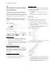
Figure 1: Front View:
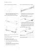
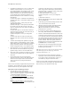
Figure 2: Back View:
I. Unpacking the Box
1. Remove all items from the shipping container. Check
each item for any damage. Keep the VT5900-SA in the
protective bag until you are ready to install it.
2. Make sure you received all the equipment you ordered. If
an item appears missing, contact your sales representative
immediately.
II. Selecting an Installation Location
Select an installation location that ensures air can circulate
freely in the unit. The VT5900-SA has cooling fans mounted
inside of the enclosure, and the rear intake vents and the front
exhaust vents should remain clear of obstructions to ensure
proper airflow.
III. Mounting on a Table or Desktop
1. Remove the VT5900-SA from its protective bag.
2. Attach the supplied adhesive feet underneath the unit.
3. Place the VT5900-SA on a table or desktop.
IV. Mounting in a Rack
The standard method of installation uses ear brackets or rails
in order to mount the VT5900-SA in a standard 19” rack using
the provided mounting materials:
• one VT5900-SA
• two ear brackets (or two slide rails and two extension
brackets)
• bag of Phillips screws (8 of #M6x12, 4 of #6-32x.312)
Required Tools
Phillips screwdriver (#2 size)
Rack Installation Procedure Using Ear Brackets
1. Remove the VT5900-SA from its protective bag.
2. Determine where the VT5900-SA will be mounted.
3. Remove any blanking panels and other equipment from
the chosen rack location.
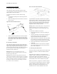
4. Install the cage nuts on the vertical mounting rails of the
rack cabinet, as shown in Figure 3 below.
Figure 3: Installing Cage Nuts:
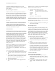
5. Locate the front of the ear brackets. (See Figure 4 below.)
Figure 4: Locating Front of Ear Brackets:
6. Attach the ear brackets to the VT5900-SA, using two of
the #6-32x.312 Phillips screws on each side. Position the
front of each bracket next to the end of the VT5900-SA
that will be facing out of the rack (see Step 7 for more
information). Tighten the screws securely.
Air intake Vents