
Virtual TapeServer SCSI-to-FC Adapter Quick Setup Guide

PN# DS41272, 608051-001
2
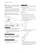
Figure 5: Attaching Ear Brackets to VT5900-SA:
7. Attach the front of the mounting brackets to the rack
using two of the #M6x12 Phillips screws for the front of
each ear bracket. Tighten the screws securely.
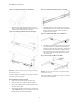
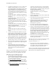
Figure 6: Attaching VT5900-SA with Ports Facing In:
Figure 7: Attaching VT5900-SA with Ports Facing Out:
Warning: To reduce the risk of injury or equipment damage,
brackets must be level.
Once the VT5900-SA is installed, you are ready to connect it
to the other system components.
Rack Installation Procedure for Rails
1. Remove the VT5900-SA from the protective bag.
2. Determine where the VT5900-SA will be mounted.
3. Remove any blanking panels and other equipment from
the chosen rack location.
4. Attach extension brackets to both sides of rack using two
of the #M6x12 Phillips screws to mount the end of each
bracket onto the rack, as shown in Figure 8.
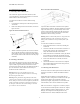
Figure 8: Attaching Extension Brackets to 19” Rack:
5. Attach the slide rails to the VT5900-SA, using two #6-
32x.312 Phillips screws on each side of the VT5900-SA.
Position the front of each rail as shown in Figure 9.
Tighten the screws securely.
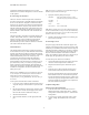
Figure 9: Attaching Slide Rails to the VT5900-SA:
6. Attach the VT5900-SA to the rack by inserting the slide
rails at the sides of the VT5900-SA into the extension
brackets you attached to the rack in Step 4. Slide the rails
into the brackets as shown in Figure 10 below until the
rails lock into place. Press in the spring latches on each
side of the VT5900-SA and then push it the rest of the
way into the rack.
Figure 10: Inserting VT5900-SA into Rack:
Warning: To reduce the risk of injury or equipment damage,
brackets must be level.
Once the VT5900-SA is installed, you are ready to connect it
to the other system components.
Front of
ear bracket
Spring Latch