
Virtual TapeServer SCSI-to-FC Adapter Quick Setup Guide

PN# DS41272, 608051-001
3
V. Connecting Devices and Cables
A. Connecting to Fibre Channel Ports
The VT5900-SA supports multi-mode (shortwave) fiber
(2.125 Gbit Dual LC connectors) through the use of external
Small Formfactor transceivers (SFFs).
To connect the VT5900-SA to a Fibre Channel storage
network:
1. Locate the Fibre Channel ports on the back panel of the
VT5900-SA.
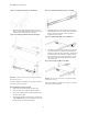
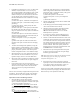
2. Remove the rubber protectors from the SFFs, as shown in
Figure 12 below.
Figure 12: Removal of SFF Protectors:
3. With the VT5900-SA powered off, connect the VT5900-
SA into the Fibre Channel environment using the appro
-
priate cabling. The FC optical connectors on the VT5900-
SA are keyed. Insert the cable connectors with the proper
orientation.
B. Connecting to SCSI Buses
The VT5900-SA supports Fast/Ultra-3 Narrow/Wide SCSI
and is factory configured to support HVD buses. Two VHDCI
68-pin D-shell, P-type connectors are located on the back
panel of the unit, allowing the unit to be attached at the end of
up to two SCSI buses. The VT5900-SA must always be
installed at the end of SCSI buses.
Warning: SCSI ports on the VT5900-SA are not hot-
pluggable. Power off the VT5900-SA whenever connecting/
disconnecting the SCSI cables.
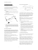
Warning: During attachment of high density SCSI cables,
please note the orientation (as shown in Figure 13) of the high
density SCSI port connectors on the back panel of VT5900-SA.
Failure to maintain appropriate orientation of the cables to
the SCSI port connectors can result in damage to the SCSI
port connectors on the VT5900-SA.
Figure 13: SCSI Cable Orientation:
Any SCSI cables used with the VT5900-SA series product
must meet SCSI 2 standards. The cables should have a VHDCI
68pin .8mm D-shell/P-type to Standard 68pin SCSI D-shell
connector at the end being attached to the HP VT5900-SA.
The type of connector at the other end of the cable will be
dependent on the device being connected.
Warning: Please be advised that failure to comply with these
minimum high-density cable specifications can result in
damage to the VT5900-SA or an operational failure of the
product.
To connect the VT5900-SA to a SCSI bus:
1. Power off the SCSI devices on this bus, including the
VT5900-SA.
2. Connect a SCSI cable to one of the SCSI connectors on
the back panel of the unit. The VT5900-SA should
always be installed at the end of the SCSI bus.
3. Make sure that the bus is terminated correctly. By default,
the VT5900-SA is automatically terminated. However,
the device at the other end of bus must also be terminated.
4. Power on the SCSI devices on this bus, but not the
VT5900-SA.
5. After all the SCSI devices on this bus have completed
their individual POST (Power-On Self Test) processes,
power on the VT5900-SA.
C. Connecting to the Ethernet Port
The RJ-45 connector on the back panel of the VT5900-SA can
be directly connected to a standard 10/100BaseT Ethernet
network.
Setting the IP network address is recommended, but not
required, in order to configure the VT5900-SA from this port.
The IP network address can be manually assigned or
dynamically assigned (using DHCP). For more about the IP
network address, refer to the user manual for this product.
Note: The VT5900-SA is configured to use DHCP by default.
For the VT5900-SA Virtual TapeServer SCSI-to-FC Adapter,
ethernet capabilities include an HTTP interface (i.e. Visual
Manager) for configuration and management from any
standard web browser. Telnet, SNMP, and FTP are also
SFF Protector
SFF