
Virtual TapeServer SCSI-to-FC Adapter User Manual


xi
List of Figures and Tables
List of Figures and Tables
Figure 1-1. Front panel of the VT5900-SA ........................................................ 1-1
Figure 1-2. Back panel of the VT5900-SA ......................................................... 1-1
Figure 1-3. VT5900-SA LEDs ............................................................................ 1-2
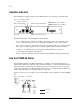
Figure 1-4. Example configuration ..................................................................... 1-2
Figure 1-5. Information processing .................................................................... 1-3
Figure 1-6. Flow of data and responses .............................................................. 1-3
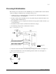
Figure 2-1. Installing cage nuts ........................................................................... 2-3
Figure 2-2. Locating front of ear brackets .......................................................... 2-3
Figure 2-3. Attaching ear brackets ...................................................................... 2-4
Figure 2-4. Mounting at front of rack ................................................................. 2-5
Figure 2-5. Mounting at back of rack ................................................................. 2-5
Figure 2-6. Attaching rails to 19” Rack .............................................................. 2-6
Figure 2-7. Attaching rails to the VT5900-SA ................................................... 2-7
Figure 2-8. Mounting VT5900-SA into rack ...................................................... 2-7
Figure 2-9. Port locations .................................................................................... 2-8
Figure 2-10. WWN/MAC ID label ..................................................................... 2-8
Figure 2-11. Configuration with tape library in FC-AL ..................................... 2-9
Figure 2-12. Fibre Channel port ......................................................................... 2-9
Figure 2-13. Removal of SFF protectors .......................................................... 2-10
Figure 2-14: High density SCSI cables ............................................................. 2-11
Figure 2-15. VT5900-SA SCSI connection ..................................................... 2-12
Figure 2-16. VT5900-SA Ethernet port ............................................................ 2-12
Figure 2-17. VT5900-SA Serial port ................................................................ 2-13
Figure 2-18. VT5900-SA power switch and connector .................................... 2-15
Figure 6-1. Visual Manager home page .............................................................. 6-3
Figure 6-2. VT5900-SA image .......................................................................... 6-3
Figure 6-3. Navigation Bar ................................................................................. 6-4
Figure 6-4. System page .................................................................................... 6-5
Figure 6-5. Serial screen ..................................................................................... 6-6
Figure 6-6. Network screen ............................................................................... 6-7
Figure 6-7. Overrides Settings screen ................................................................. 6-8
Figure 6-8. SNMP screen .................................................................................... 6-9
Figure 6-9. Active Fabric screen ...................................................................... 6-11
Figure 6-10. User screen ................................................................................... 6-12
Figure 6-11. Real Time Clock screen ............................................................... 6-13
Figure 6-13. Host Statistics Threshold Settings screen .................................... 6-14
Figure 6-13. Reset to Factory Defaults screen .................................................. 6-15
Figure 6-14. Ports page .................................................................................... 6-16
Figure 6-15. FC Port 0 screen ........................................................................... 6-17