
Virtual TapeServer SCSI-to-FC Adapter User Manual


9-1
Chapter 9
Troubleshooting
Various problems can arise when configuring and using the VT5900-SA. This section is provided
to help guide the user through some of the basic methods of identifying faults in the setup and
configuration of the unit.
Most problems are found in the initial installation. In general, it is wise to check all connections
and review the configuration before proceeding with further trouble analysis. Simplify the
installation if possible, reducing it to the most basic configuration then adding elements one at a
time and verifying the operation at each step.
Indicators
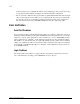
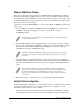
The VT5900-SA is equipped with rear panel LED indicators for monitoring overall unit status.
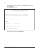
Figure 9-1. VT5900-SA LEDs
The LED functionality of the VT5900-SA is detailed below:
• Power and Fault (Pwr)—This indicator is a bi-color LED. When green, this indicator shows
that power is currently active. Lack of power indication suggests that the unit is turned off, a
problem with the power supplied to the unit, or an internal problem with the unit. When this
indicator is amber, this indicator shows that the VT5900-SA detects a fault condition. Faults
can occur as a result of Power On Self Test (POST) failure or operational failures. It is normal
for this indicator to flash on when the unit is powered up or reset. If the fault indicator stays lit,
contact your product support representative.
• Fibre Channel (Lnk/Act)—When lit green, the upper indicator signifies a good Fibre Channel
link on the port. When lit green, the lower indicator signifies Fibre Channel port activity. If the
Link indicator fails to light at all, or if the Activity indicator stays continually lit without
corresponding SCSI bus activity, there may be a problem with the Fibre Channel
configuration. Verify the Fibre Channel configuration.
• SCSI Bus (0, 1)—When lit, these green indicators signify SCSI activity on the bus
corresponding to the number of the indicator. Activity should be indicated only occur briefly
during power up or configuration, and relatively often when the unit is transferring data. If an
Power
Ethernet Link Status
Ethernet Activity
Fibre Channel Activity
Fibre Channel Link Status
HVD SCSI Activity for Bus 0
HVD SCSI Activity for Bus 1