
Virtual TapeServer SCSI-to-FC Adapter User Manual


A-1
Appendix A
RJ-11 to DB-9 Serial Pin Assignments
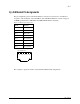
The pin assignments given for the RJ-11 serial connection are in reference to the serial receptacle
on the rear panel of the VT5900-SA. Use an RS-232 null modem cable to connect the VT5900-SA
to the host system.
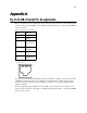
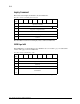
Figure A-1. RJ-11 pin assignments
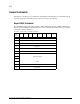
In conjunction with the pin assignments provided for the RJ-11 receptacle on the rear panel of the
VT5900-SA, following are the corresponding pin out assignments for a DB-9 serial connector
used to connect the other end of the serial cable to a terminal, or a computer running terminal
emulation software.
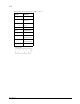
The pin assignments given in Figure A-2 for the DB-9 serial connection are in reference to the
serial connector at the end of the cable. Use an RS-232 null modem cable to connect the VT5900-
SA to the host system.
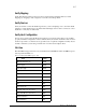
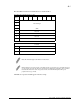
Pin No. Function
Pin 1 No Connection
Pin 2 Ground
Pin 3 Transmit Data
from VT5900-
SA
Pin 4 Receive Data to
VT5900-SA
Pin 5 RTS (Ready to
Send)
Pin 6 CTS (Clear to
Send)
RJ-11 modular recepticle pin
assignments
1
Front View
23456