
Virtual TapeServer SCSI-to-FC Adapter User Manual


1-2
Chapter 1: Introduction
Operation Indicators
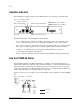
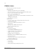
The VT5900-SA is equipped with rear panel LED indicators for monitoring overall unit status.
Figure 1-3. VT5900-SA LEDs
The LED functionality of the VT5900-SA is detailed below:
• Power and Fault (Pwr)—This bi-color LED is green to show that power is currently active
and is continuously amber-colored to show that the VT5900-SA detects a fault condition.
• Fibre Channel (Link/Act)—When lit green, the upper indicator signifies a good Fibre Channel
link on the port. When lit green, the lower indicator signifies Fibre Channel port activity.
• SCSI Bus (0, 1)—When lit, these green indicators signify SCSI activity on the bus
corresponding to the number of the indicator.
• Ethernet (10/100)—When lit, these green indicators signify Ethernet link status and activity.
How the VT5900-SA Works
The VT5900-SA translates the Fibre Channel Protocol (FCP) to and from the SCSI Protocol—
transparently transferring commands, data, and status information—so that both the Fibre Channel
(FC) and SCSI devices and hosts can communicate with each other. Interconnection is provided
between two SCSI buses and a Fibre Channel Arbitrated Loop or Switched Fabric and makes use
of Fibre Channel’s ability to encapsulate SCSI protocol packets.
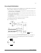
Figure 1-4 shows a host (on an FC loop) accessing SCSI tape drives and libraries via the VT5900-
SA.
Figure 1-4. Example configuration
Power
Ethernet Link Status
Ethernet Activity
Fibre Channel Activity
Fibre Channel Link Status
HVD SCSI Activity for Bus 0
HVD SCSI Activity for Bus 1
SCSI
Fibre Channel