
Virtual TapeServer SCSI-to-FC Adapter User Manual


2-10
Chapter 2: Getting Started
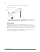
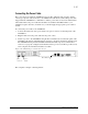
2. Remove the rubber protectors from the SFFs, as shown in Figure 2-13.
Figure 2-13. Removal of SFF protectors
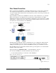
3. With the VT5900-SA powered off, connect the VT5900-SA into the Fibre Channel environ-
ment using the appropriate cabling. The FC optical connectors on the VT5900-SA are keyed.
Be sure to insert the cable connectors in the proper orientation.
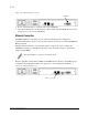
SCSI Connection
The VT5900-SA can support Fast/Ultra-3 Narrow/Wide SCSI, depending on the specific
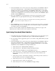
configuration. The VT5900-SA is factory configured to support HVD buses. Two VHDCI 68-pin
D-shell, P-type connectors are located on the rear panel of the unit, allowing the unit to be attached
at the end of up to two SCSI buses. The VT5900-SA must always be installed at the end of SCSI
buses.
The VT5900-SA supplies termination power (TERMPWR) to each SCSI bus. An internal self-
resetting fuse in the TERMPWR will reset after a fault is cleared.
SFF Protector
SFF