
X25AM Configuration and Management Manual

PTrace for the X25AM Subsystem
X25AM Configuration and Management Manual—523424-004
6-13
Tracing Level 3
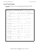
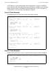
If the DTE does not receive a frame within the level-2 timeout value, the DTE sends an
RR command frame with the P bit set, demanding that the remote side respond. If the
DTE receives nothing within the level-2 retries value, level 2 initiates error recovery.
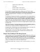
Tracing Level 3
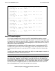
The packet level follows the X.25 protocol as required by the ITU-T. The protocol
describes the basic handshaking used to send and acknowledge data for a number of
virtual circuits multiplexed over the same Data Link Layer (level 2). X.25 circuits are
defined by a distinct logical channel number (LCN), which is a 2-byte field that
immediately follows the address and control bytes of a level-2 I-frame.
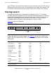
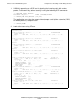
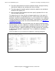
Figure 6-2 shows an X.25 packet.
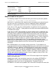
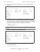
Packet Type identifies the kind of packet. See Table 6-4 for the most significant bits
(MSBs), the least significant bits (LSBs), and the hexadecimal values of the different
packet types.
Figure 6-2. X.25 Packet
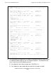
Table 6-4. Packet Types (page 1 of 2)
Call Request 0000 1011 0B
Call Accepted 0000 1111 0F
Clear Request 0001 0011 13
Clear Confirmed 0001 0111 17
Diagnostic 1111 0001 F1
Interrupt 0010 0011 23
Interrupt Confirmed 0010 0111 27
Reset 0001 1011 1B
Reset Confirmed 0001 1111 1F
Restart 1111 1011 FB
Restart Confirmed 1111 1111 FF
Data* RRRM SSS0
* RRR = N(R) acknowledges all data packets received -1. SSS = N(S), number of data packets sent. M = More
bit (more data follows).
VST0602.vsd
7E A C
Logical
Channel Number
Packet
Type
Optional
Data...
FCS 7E
X.25
Packet