
X25AM Configuration and Management Manual
PTrace for the X25AM Subsystem
X25AM Configuration and Management Manual—523424-004
6-16
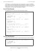
Sample Trace Reading of Calls Being Cleared
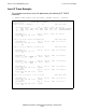
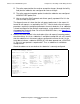
The first 2 bytes of the packet describe the LCN 001, bits 4:16. The first 2 bytes
distinguish the circuit from the many that can be multiplexed on a common level-2 link
layer. Bits <0:3> are packet control identifiers, such as the D bit (delivery packet) and
the Q bit (PAD packet identifier). In X25AM, an LCN is roughly equivalent to a
subdevice.
The third byte of the packet, 0B, identifies the type of packet. In the example above, a
call request packet has arrived. The ensuing data depends on the type of packet. Here,
there is no called address (because the NETID happens to be TELENET). When this
packet comes into the local level 3, it must first match the configured line NETADDR
(set here at 0). Then, the remaining two digits are passed to level 4 to be matched to a
subdevice’s configured port number. Because a subdevice is configured to match the
incoming address, the local level 3 sends the call accepted packet in response, shown
at sequence #33.
At this point, the circuit is connected and data can be transferred for LCN 1. The full
address of the subdevice is no longer needed because the LCN number represents the
connection and is sufficient to identify the subdevice from now on.
At sequence #113, X25AM initiates circuit disconnection by issuing a clear packet (the
initiation begins because the application issued a CONTROL 12).
At sequence #121, the last trace record shows the network’s response: a clear
confirmed packet. At this point the circuit is cleared and the LCN (and thus the
subdevice) are free to be used again.
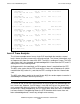
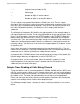
Sample Trace Reading of Calls Being Cleared
Trying to establish a call is a common problem in X25AM. X25AM and host DCEs clear
calls for several reasons. When a call is cleared, take a trace. You can usually pinpoint
the problem by looking at the packets. One side of the line issues a call request packet
to establish a call. The other side acknowledges the call with a call accept packet.
Either side can reject the call by returning a clear packet. Sometimes the clear packet
contains an extra byte of data, called a clear diagnostic byte.
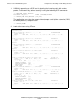
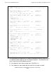
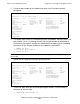
The following example (Steps 1 through 9) shows a call being cleared as a result of a
failure:
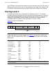
001 Logical channel number (LCN)
0B Packet type
2 Number of digits in source address
0 Number of digits in destination address