
HP OneView 1.0 User Guide
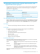
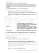
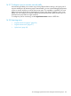


Figure 12 Relationship of a logical interconnect group to a logical interconnect
Logical Interconnect LI1
<create> <create> <create>
Enclosure Group
enclosure Type - c7000
Stocking Mode - enclosure
LIG
Logical Interconnect Group A
Domain Networks: Eth1, Eth2, SanA, SanB
Uplink Sets -
- 1 - Blue Network, bay1.x1 & bay2.x1
Interconnect Maps
Enclosure A
638526-B21, Int1
571956-B21, Int3
EMPTY
EMPTY
EMPTY
EMPTY
571956-B21, Int4
638526-B21, Int2
I/O Bay Logical Interconnect Group
1
logicalInterconnectGroupA
logicalInterconnectGroupA
2
4
3
Location Interconnect Types(s) Logical Downlink
Enc2. Bay2 638526821
571956B21
Logical DownlinkA
Enc3. Bay3 Logical DownlinkA
Enc4. Bay4 571956B21 Logical DownlinkA
Logical DownlinkAEnc1. Bay1 638526821
Location Int. Int. Type(s)
EncA. Bay1
EncA. Bay2
EncA. Bay4
Int1 638526B21
638526B21Int2
Int3
Int4
EncA. Bay3
571956B21
571956B21
LD A
LD A
LD B
LD C
LD
Logical Interconnect LI2
Enclosure B
638526-B21, Int1
571956-B21, Int3
EMPTY
EMPTY
EMPTY
EMPTY
571956-B21, Int4
638526-B21, Int2
Location Int. Int. Type(s)
EncB. Bay1
EncB. Bay2
EncB. Bay4
Int1 638526B21
638526B21Int2
Int3
Int4
EncB. Bay3
571956B21
571956B21
LD A
LD A
LD B
LD C
LD
Logical Interconnect LI3
Enclosure C
638526-B21, Int1
571956-B21, Int3
EMPTY
EMPTY
EMPTY
EMPTY
571956-B21, Int4
638526-B21, Int2
Location Int. Int. Type(s)
EncC. Bay1
EncC. Bay2
EncC. Bay4
Int1 638526B21
638526B21Int2
Int3
Int4
EncC. Bay3
571956B21
571956B21
LD A
LD A
LD B
LD C
LD
Domain Networks: Eth1, Eth2, SanA, SanB
Uplink Sets: ...
Interconnect Maps
Domain Networks: Eth1, Eth2, SanA, SanB
Uplink Sets: ...
Interconnect Maps
Domain Networks: Eth1, Eth2, SanA, SanB
Uplink Sets: ...
Interconnect Maps
logicalInterconnectGroupA
You can create a logical interconnect group independently of adding an enclosure, or you can
edit the logical interconnect group that the appliance creates when you add the enclosure to the
appliance. When you add the first enclosure to the appliance, the preliminary logical interconnect
group is based on the physical interconnects in that enclosure and is created with the following
properties:
• Existing interconnect types in their existing positions
• All physical uplink ports disabled except for stacking links
You can edit this logical interconnect group, and when the configuration is complete, an enclosure
group is created and associated with this logical interconnect group.
If you assign an enclosure group (which includes a logical interconnect group) to an enclosure in
which the interconnects installed in the enclosure do not match the logical interconnect group, each
interconnect reports its state as unmanaged. The physical interconnect configuration in the enclosure
must match the logical interconnect group before an interconnect can be managed.
To delete a logical interconnect group, you must delete the associated enclosure group.
16.2.5 About SNMP settings
Network management systems use SNMP (Simple Network Management Protocol) to monitor
network-attached devices for conditions that require administrative attention. By configuring settings
on the Logical Interconnect Groups and Logical Interconnects screens, you can enable third-party
SNMP managers to monitor (read-only) network status information of the interconnects.
The SNMP manager typically manages a large number of devices, and each device can have a
large number of objects. It is impractical for the manager to poll information from every object on
every device. Instead, each agent on the managed device notifies the manager without solicitation
by sending a message known as an event trap.
The appliance enables you to control the ability of SNMP managers to read values from an
interconnect when they query for SNMP information. You can filter the type of SNMP trap to
16.2 Managing logical interconnects and logical interconnect groups 127