Technical Whitepaper HP OneView Deployment and Management Guide How To Deploy and Manage OneView, Version 1.0 Table of contents Introduction .................................................................................................................................................................................... 3 Features in HP OneView 1.0 ...................................................................................................................................................
Technical white paper | HP OneView Deployment and Management Guide Section M11: Changing User Permissions ......................................................................................................................... 90 Section M12: Adding a New Blade to an Enclosure and Discovering New Server Hardware Types ..................... 91 Section M13: Adding New Racks Based on Location Discovery Services ...................................................................
Technical white paper | HP OneView Deployment and Management Guide Introduction Welcome to the Quick Start, Deployment and Management Guide for HP OneView. HP OneView provides a simple, consumer-inspired user experience that dramatically accelerates everyday tasks. By changing the focus from ‘how devices are managed’ to ‘how people work,’ HP OneView delivers a softwaredefined management platform that is extensible and easy to use.
Technical white paper | HP OneView Deployment and Management Guide Manage DL Servers Add DL ProLiant rackmount servers for inventory and health Alert and Monitor Systems in the DataCenter iLO 4 traps automatically configured on import, no OS agents required Environmental Management Model and analyze power, cooling and location of your HP IT equipment Secure Appliance Integrate the appliance into your Active Directory or OpenLDAP infrastructure Visualizing the DataCenter Visualize your data center’
Technical white paper | HP OneView Deployment and Management Guide Supported Interconnects • HP Virtual Connect FlexFabric 10Gb/24-Port Module • HP Virtual Connect Flex-10 10Gb Ethernet Module • HP Virtual Connect Flex-10/10D Ethernet Module Hardware Firmware Minimum Requirements Table 3 shows the minimum firmware requirements needed to successfully import an enclosure. Firmware will be updated via the appliance to the required versions later in this document. Table 3.
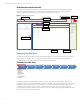
Technical white paper | HP OneView Deployment and Management Guide HP OneView User Interface Overview The entirely new HP OneView user experience is significantly improved from previous generations of HP Management software (eg. HP System Insight Control.) The HP OneView user interface is built using modern web programming languages, HTML5 and CSS3. Below is an example of what the User Interface looks like (UI.) Figure 1.
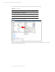
Technical white paper | HP OneView Deployment and Management Guide Prior to continuing with this document, please make sure you have completed the following: Table 6. Installation Checklist Task Completed? (Y|N) Have a supported vSphere 52 host for appliance Have Static IP Address, or DHCP Static Reservation Have DNS A and PTR Records created Figure 2. Obtain the Virtual Machine IP Address As shown in Figure 2.
Technical white paper | HP OneView Deployment and Management Guide Figure 3. Appliance Startup and Initialization Screen using the vSphere Client Figure 4.
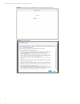
Technical white paper | HP OneView Deployment and Management Guide Figure 5. HP Support Access Opt-In The HP Support Access Opt-In, as shown in Figure 5, is used for the HP GCC remote access when the appliance is in an unhealthy state, and core services cannot start. By opting out, this also disables the ability to reset the appliance Administrator account password if ever lost. Table 7. Default Credentials UserName Password Administrator admin Figure 6.
Technical white paper | HP OneView Deployment and Management Guide Figure 7. Change Administrator Password After providing the new Administrators password, you will be prompted for Appliance Networking configuration. You will need the following: • Appliance Hostname (e.g. hponeview.contoso.com) – If you specify an FQDN, verify valid A and PTR records exist. The appliance will perform an nslookup of the FQDN and IP address and report an appliance warning if neither are available.
Technical white paper | HP OneView Deployment and Management Guide Figure 8. Configure Appliance Networking After clicking OK, the appliance will go and configure those parameters. If you selected Static for the IP Address Assignment, you should be redirected to the new IP address. Please accept the certificate security warnings during the redirection, as a new SSL certificate is generated from the FQDN.
Technical white paper | HP OneView Deployment and Management Guide Section D2: Firmware Repository The HP OneView appliance ships with a default SPP that contains the necessary firmware to successfully import and manage an enclosure. It is unnecessary to upload an SPP into the appliance, unless a custom baseline (created by HPSUM6) is required. 12 1. Select the Top Level Menu, and navigate to Firmware Bundles in the console 2. Examine the default SPP Baseline 3.
Technical white paper | HP OneView Deployment and Management Guide 4. The SPP upload will being. You can click the blue Close button in the lower right, as that will only close the dialog box and not cancel the upload. Note Do not close the browser window until the Firmware Upload task has completed. You can click on the Close button in the Add Firmware Bundle dialog as the upload is a background thread within the web application.
Technical white paper | HP OneView Deployment and Management Guide 2. Open the Actions menu, and select Add License. 3. Paste in your license key in the dialog box and click Add to apply the license. 4. On the Licenses page, verify that your license count has increased.
Technical white paper | HP OneView Deployment and Management Guide appliance, as HP OneView does not support Active/Active Virtual Connect networking configuration. Similar to Virtual Connect provisioning all Ethernet Networks to all Ethernet modules within a Virtual Connect Domain, HP OneView provisions all defined Ethernet Networks to all managed Ethernet-capable modules. Network Sets are aggregated networking objects that contain Networks.
Technical white paper | HP OneView Deployment and Management Guide 2. Once on the Networks screen, click the +Create Network button on the far left. 3. In the new window, provide the Name, select Ethernet as the Type, provide the VLAN ID (which must be unique within the HP OneView appliance), and bandwidth settings. Smart Link will automatically be selected by default. The Name is not case-sensitive, can contain spaces and special characters.
Technical white paper | HP OneView Deployment and Management Guide Fabric Attached Network 1. From the Top Level Menu, select Networks, then select the +Create Networks button. 2. In the new window, provide the Name, select Fibre Channel as the Network Type, select Fabric Attach as the Fabric Type, and modify Bandwidth allocation, Uplink Speed, Login Redistribution as needed.
Technical white paper | HP OneView Deployment and Management Guide 2. In the new window, provide the Name, select Fibre Channel as the Network Type, select Direct Attach as the Fabric Type, and modify Bandwidth allocation and Uplink Speed. Note By selecting the Direct Attach Fabric Type, you can assign any of the available X1-X4 ports on a Virtual Connect Flexfabric module to an HP 3Par StoreServ array. 3.
Technical white paper | HP OneView Deployment and Management Guide 2. Once on the Network Sets screen, click the +Create Network Set button on the far left. 3. On the Create Network Sets screen, provide a name, then click the Add Networks button to select the networks to add.
Technical white paper | HP OneView Deployment and Management Guide 20 4. You can search for a network, or either click SHIFT/CTRL+Left Mouse Click to select which will either select all in section, or multi-select the networks to add. 5. After clicking Add, you can select the specific network that will be the Native VLAN, or the default untagged network for the Servers Network Connection. This is typically used for PXE traffic.
Technical white paper | HP OneView Deployment and Management Guide Create Logical Interconnect Group 1. Select the Top Level Menu, and choose Logical Interconnect Group (LIG). 2. Once on the LIG screen, select the +Create Logical Interconnect Group button. 3. Provide a name to best describe the template. Use terms like Production or Dev to help describe the Logical Interconnect Group. 4. Click the Add interconnect button to add modules to Bays 1 and 2.
Technical white paper | HP OneView Deployment and Management Guide automatically select the correct module. Creating Uplink Sets 1. Click the Add uplink set button. 22 2. On this window, we will create an Ethernet Type Uplink set representing an Active/Standby configuration. Provide a Name, select Ethernet as the Type. 3. Click the Add networks button to select the networks to add.
Technical white paper | HP OneView Deployment and Management Guide by searching. 4. Make sure to mark the appropriate network as Native if the VLAN on the upstream switch is also the Native or Default VLAN.
Technical white paper | HP OneView Deployment and Management Guide 24 5. Click the Add ports button to add uplink ports. 6. Select at least one port from each Ethernet Module. To quickly add multiple Uplink Ports, first search for a common port (eg. X5), select them, click the Add+ button, then change the search to another port (eg. X6) and click the Add button. 7. After you have added the Uplink Ports to your Uplink Set, click the Create button.
Technical white paper | HP OneView Deployment and Management Guide Creating Fibre Channel Uplink Sets (Optional) 1. Click the Add uplink set button to add SAN Fabrics.
Technical white paper | HP OneView Deployment and Management Guide 2. Select Fibre Channel as the Type, provide a Name, select the SAN Fabric Name, Interconnect, and then select which ports are to be linked. Note The Interconnect field will display the switch device by its Bay ID. 26 3. Click the Create+ button. 4. Repeat to create the redundant SAN Fabric. Notice that the other Fabric is filtered from view. 5. Click the Create button.
Technical white paper | HP OneView Deployment and Management Guide 6. If you wish to create another Uplink set, repeat the above steps, or click the Create button. Reviewing Logical Interconnect Group Configuration 1.
Technical white paper | HP OneView Deployment and Management Guide 2. Scroll down to bring the Logical Interconnect Group section into view, and mouse over of the Uplink sets. Examine the relationship of the Uplink set to the physical modules and their uplink ports. 3. Scroll down to bring the Logical Uplinks section into view. Examine the Logical Uplinks and their relationship to the assigned Networks.
Technical white paper | HP OneView Deployment and Management Guide 2. Click on the Create Enclosure Group button 3. In the Create Enclosure Group screen, provide a Name, and select the appropriate Logical Interconnect Group you created earlier. Notice that if only a single Logical Interconnect Group exists, it will be selected by default. 4. Click the Create button to create the Enclosure Group, or Create+ to create the Enclosure Group and additional Enclosure Groups.
Technical white paper | HP OneView Deployment and Management Guide Enclosure Import process will also discover any device in the enclosure’s Device Bays, and attempt to configure the supported iLO’s for management (SNMP, NTP, HP SIM SSO Certificate, create a special user account _HPOneViewAdmin) and license the iLO’s and servers based on the License Intent setting in the Add Enclosure screen. Table 9.
Technical white paper | HP OneView Deployment and Management Guide version within the SPP. 4. HP OneView provides audit tracking within the appliace. By clicking the gear in the lower left corner, HP OneView shows you to what you have changed in the dialog screens. 5. Once the enclosure information has been verified, the appliance will begin its discovery process.
Technical white paper | HP OneView Deployment and Management Guide During this time, the appliance will validate if the OA firmware meets the minimum requirement.
Technical white paper | HP OneView Deployment and Management Guide Clicking on the Details link will take you to the Activity view of the enclosure, were you can examine the task and subtask details. If the firmware was out of date, the Activity window would display the sub-tasks generated. Below is a sample screenshot.
Technical white paper | HP OneView Deployment and Management Guide 34 6. After the Add Enclosure task has completed, the Enclosure State should read Configured. 7. After adding the first enclosure, there might be a Warning status message, indicating the appliance encountered problems with the servers during discovery.
Technical white paper | HP OneView Deployment and Management Guide Clicking on the Details link will take you to the Activity page of the enclosure. In the following example, HP OneView is reporting no licenses are available. Instead, the 60-day “trial” license will be applied. 8. Repeat the above steps to add more enclosures. Examine Imported Resources After you have successfully imported the enclosure, you will want to verify all the resources in the enclosure have been imported.
Technical white paper | HP OneView Deployment and Management Guide 3. Select the Top Level Menu, and choose Logical Interconnects 4. The Logical Interconnect view is how the VC Modules within the Enclosure are configured based on the Logical Interconnect Group you defined earlier. Server Hardware 1. Select the Top Level Menu, and choose Server Hardware.
Technical white paper | HP OneView Deployment and Management Guide 2. In this section, you will see the discovered servers listed in the left panel. Selecting a specific server will provide you with the details. Server Hardware Types Server Hardware Types are the unique server hardware configurations discovered during the addition of imported enclosures.
Technical white paper | HP OneView Deployment and Management Guide 2. You can edit a Server Hardware Type, but only to rename it or add a description. Examine Relationships Let’s examine the HP OneView mapping and relationship capabilities. We’ll look at the Enclosure, blade and Networks. 38 1. Navigate to Enclosures in the console. 2. To access the Map View, you can click on the Map button, or select Related from the sub-menu.
Technical white paper | HP OneView Deployment and Management Guide 3. Within the Map view, hover over objects to see how the relationships are built. In the following example, you can see the relationship built when moused over the Enc1 Enclosure. Clicking on an object will navigate you to that objects Map View.
Technical white paper | HP OneView Deployment and Management Guide 40 4. Mouse over and locate one of your blade servers. Notice the relationship between the Enclosure, Server Hardware Type, and Interconnect Bays. Click on the Server object. 5. After selecting one of your servers, notice the Map View now displays different information. Hover over the Server Hardware and notice the relationship shown. 6. Lastly, we will examine Network relationships.
Technical white paper | HP OneView Deployment and Management Guide 7. Select an available Network, and click the Map View button. Mouse over the network, and examine the relationship tree that is built. Section D6: Add ProLiant DL Gen8 Server First Time Setup Configure Networking Discover Hardware Upgrade Firmware Server Profiles Environment Management Appliance Security • Import ProLiant DL Gen8 HP OneView supports adding a ProLiant Gen8 DL for health and alert management only.
Technical white paper | HP OneView Deployment and Management Guide 42 2. In the Server Hardware screen, click the +Add Server Hardware button. 3. In the Add Server Hardware screen, add the first DL380 Gen8 server’s iLO FQDN or IP Address, along with Administrator credentials. Click the Add button to add the DL server, or select the Add+ button to continue adding DL Gen8 servers.
Technical white paper | HP OneView Deployment and Management Guide 4. After clicking the Add button, HP OneView will being to discover the server, and configure the iLO for management. 5. Once the server is added, you can power it on and launch the Remote Console from the Actions menu. 6. The server is now configured for element management by HP OneView.
Technical white paper | HP OneView Deployment and Management Guide 1. Navigate to Enclosures from the Top-level Menu. Select Firmware in the submenu. 2. Examine what is Installed versus what is available in the Firmware Baseline. Managing Virtual Connect Firmware HP OneView provides the ability to manage Virtual Connect firmware from multiple locations; at the Logical Interconnect or Enclosure level.
Technical white paper | HP OneView Deployment and Management Guide 2. In the Logical Interconnects view, validate the [ENC-Name]-LI Logical Interconnect is selected, then the Actions menu select Update Firmware. 3. On the Update Firmware on [ENC-NAME]-LI window, select the Firmware Baseline, and select Update Firmware (stage + activate) action. The other two options are for staging firmware to initiate a manual activation of the Virtual Connect firmware.
Technical white paper | HP OneView Deployment and Management Guide 4. Clicking OK will begin the firmware update process. However, if you want to examine the individual update process for each Virtual Connect module, click the Details link in the Activity bar.
Technical white paper | HP OneView Deployment and Management Guide 5. Once the firmware update has completed, examine the Firmware section, and see that it should show the Firmware Baseline assigned, the Installed and Baseline versions.
Technical white paper | HP OneView Deployment and Management Guide 2. Once on the Server Profiles screen, select the +Create Profile button 3. Provide a Name and Description for the Server Profile. Select Unassigned for the Server Hardware, and the Server Hardware Type and Enclosure Group will be accessible. Attach a Firmware Baseline to the Server Profile. When selecting either the Server Hardware Type or Enclosure Group will filter the assignable Server Hardware section.
Technical white paper | HP OneView Deployment and Management Guide Network Connections to the Server Profile. Note You can specify which FlexNIC to assign the Network Connection to, or leave it at the default of Auto. Auto will apply the same Network Connection to Adapter mapping Virtual Connect does today. Do know that you cannot create a FlexNIC B, C or D without first creating FlexNIC A.
Technical white paper | HP OneView Deployment and Management Guide A. (Optional) If you wish to configure FC Boot From SAN (BFS), change the Boot setting from Not Bootable to either Primary or Secondary. You will need to provide the Target WWN and Host LUN ID in the respective fields. 6. Modify the Boot Order if necessary. 7. Modify the following, or customize your own BIOS Settings A. Add a Custom Post Message under the Server Asset Text section. E.g. “HP ONEVIEW ROCKS!” B.
Technical white paper | HP OneView Deployment and Management Guide Note If the server hardware only contains a single CPU, you will need to change the HP Power Profile setting to Custom, and then change Intel QPI Link Power Management to its default value, otherwise the Server Profile will fail to apply. This BIOS setting is only available on systems that contain multiple CPUs. 8. Leave the Advanced section as default, which would be Virtual Managed Addresses. 9. Click Create. 10.
Technical white paper | HP OneView Deployment and Management Guide 11. In the Copy Profile screen, provide a Name, specify the Server Hardware that you will assign this Server Profile to, then click the Create button. Note The Server Hardware list will be filtered based on the Server Hardware Type and Enclosure Group that the Server Profile Template was configured for. You cannot change them in the Copy Profile screen. 12.
Technical white paper | HP OneView Deployment and Management Guide 13. Either select Server Hardware from the top level menu, or the Server Hardware link in the Server Profile to be taken directly to the Server Hardware view. 14. From here, you can launch the iLO Remote Console, select the Actions menu, and then Remote Console to watch the server boot into Intelligent Provisioning to configure the BIOS and deploy a firmware policy if specified.
Technical white paper | HP OneView Deployment and Management Guide 16. After the server completes it’s POST, the server will be automatically instructed to boot into Intelligent Provisioning to apply the SPP Baseline. 17. Once the firmware update has completed, the server’s Power State will change to Off. You are now able to install the OS on your server. Create Assigned Profile: One-Off Server Profile 1. Select the main menu option in the upper left, and choose Server Profiles. 2.
Technical white paper | HP OneView Deployment and Management Guide Section D9: Environmental Management First Time Setup Configure Networking Discover Hardware Upgrade Firmware Server Profiles Environment Management Appliance Security With HP OneView, you can optimize the power and cooling requirements of your data center efficiently.
Technical white paper | HP OneView Deployment and Management Guide Adding DLs to rack without LDS If LDS is not present, racks are not automatically created for DL servers. DL servers may be added to racks previously created via enclosure discovery or racks may be created manually and have servers added to them. For either option, begin by navigating to the Racks screen. 1. To go to the Racks screen, select Racks in the main menu. 2.
Technical white paper | HP OneView Deployment and Management Guide rack and edit the device details. To place a device, drag and drop it in the desired location. 5. Once the rack has been configured, select Add to complete the setup or Add + if additional racks need to be created. Creating a data center HP OneView allows you to describe the physical locations of your racks and systems within your data center.
Technical white paper | HP OneView Deployment and Management Guide the default data center indicating it has not been configured. 58 3. If you wish to use the default Datacenter 1 for your actual data center, resolve the warning message by editing Datacenter 1 and renaming/resizing it to match the data center floor (or portion thereof) you are going to be managing with HP OneView. This process is described in subsequent steps.
Technical white paper | HP OneView Deployment and Management Guide 5. To edit an existing data center, select Edit in the Layout section of data center page. 6. The Layout panel of the Edit screen allows you to drag & drop racks on the grid from a overhead view. 7. For physically accurate posititioning not aligned with the grid lines, enter the position and angle in the rack positioning popup.
Technical white paper | HP OneView Deployment and Management Guide 8. To remove any racks that are not part of the data center, drag them back to the unpositioned list or select them and click the Remove link in the popup. 9. Once editing of the data center is complete, select the OK button to return to the data center screen to view the 3D model of the data center. Configuring power delivery topology for the data center Configuring the the physical setup for your data center is only half the picture.
Technical white paper | HP OneView Deployment and Management Guide 2. To add HP iPDUs that power your previously discovered equipment, on the Power Deliver Device screen select + Add power delivery device. 3. Enter the FQDN or IP address along with the login creditials needed for discovery. 4. Once the iPDUs have been discovered, view the rack in which the iPDU-powered equipment resides. The iPDUs will be automatically depicted in the rack layout. 5.
Technical white paper | HP OneView Deployment and Management Guide Adding 3rd Party PDU’s or non-HP iPDU’s 1. If an iPDU is not being used, create one or more Rack PDUs to represent power capacity in the rack. On the Power Delivery Device screen, select + Add power delivery device. 2. On the Add Power Delivery Device screen, select Rack PDU and specify the properties that will represent your PDU and the power capacity it provides. 3.
Technical white paper | HP OneView Deployment and Management Guide 1. Select the Unmanaged Device Top Level Menu. 2. Once on the Unmanaged Devices screen, select the +Add unmanaged device button. 3. Enter the specified information to represent the unmanaged device. Specify the maximum power value for the device to enable capacity and consumption analysis of your power delivery system. Once all information is completed, click the Add or Add+ button. 4.
Technical white paper | HP OneView Deployment and Management Guide You will need the following prior to configuring Active Directory settings within the appliance: Table 10.
Technical white paper | HP OneView Deployment and Management Guide 3. Within the Edit Security window, click the Add directory button. 4. In the Add Directory window, you will need to specify the following: • Directory Name • Directory Type • Search Context – Field 1: CN for Active Directory, UID for LDAP Directories – Field 2: Organizational Unit in Distinguished Name format (i.e. OU=Admins,OU=Contoso) – Field 3: Top Level Domain Name in Distinguished Name format (i.e.
Technical white paper | HP OneView Deployment and Management Guide 5. 66 After the Directory has been configured, go back and Edit Security to set the Default Directory, and click OK to save the settings.
Technical white paper | HP OneView Deployment and Management Guide 6. Next, navigate to Users and Groups from the main menu. 7. In the Users and Groups view, select the Actions menu and choose Add Directory User or Group 8. In the Add Directory User or Group screen, provide the credentials to authenticate. Once authenticated, begin typing the directory group name in the Group Name field. Select the group, and specify its role.
Technical white paper | HP OneView Deployment and Management Guide 9. Repeat the same steps to add the remaining Directory Groups. 10. After you have configured your Directory Groups, you should log out by clicking the User button in the upper right of the UI and select Logout. 11. On the logon page, you will notice a new field to choose. This is the Directory chooser. You can select from the configured Directories and Local (if Local was not disabled in your Directory configuration.
Technical white paper | HP OneView Deployment and Management Guide 12. Log into appliance with a Server Admin user account 13. Navigate to Networks from the Top Level Menu, and notice the +Create Network button and Actions menu Networks from the Top Level Menu, and notice the +Create Network button and Actions menu are unavailable. 14.
Technical white paper | HP OneView Deployment and Management Guide 15. Navigate to Server Profiles from the Top Level Menu, and notice the +Create Server Profile button and Actions menu is no longer available. Maintaining Your Environment This segment will give you examples of how to maintain your HP OneView appliance. It will cover the regular maintenance tasks that an administrator will encounter.
Technical white paper | HP OneView Deployment and Management Guide 3. The Utilization panel located within the details pane shows the metrics available for monitoring for the resource. The utilization metrics available to be monitored depends on the resource type: • Server hardware: CPU, power (including power cap) and temperature • Enclosures: power (including power cap settings) and temperature • Power Delivery Devices: power 4.
Technical white paper | HP OneView Deployment and Management Guide 5. Selecting the Utilization panel heading or selecting Utilization from the view menu allows display and navigation of all available history of a specified metric. OR 6. Once selected, the details pane will show the first available metric for the device expanded. By default the last 24 hours of information is shown on the graph. However, the date bar below the graph allows selecting any available date range to be displayed .
Technical white paper | HP OneView Deployment and Management Guide 7. Custom graphs can also be created. This custom graph allows two metrics to be plotted on the same graph allowing comparison between the metrics. 8. HP OneView allows you to view areas in your data center that are insufficiently cooled due to various reasons such as poor airflow, concentration of excessive heat output, or wrap-around airflow at the ends of aisles.
Technical white paper | HP OneView Deployment and Management Guide • Lack of power delivery redundancy to devices attached to power delivery devices 1. Select the main menu option in the upper left, and choose Activity. 2. This page is the master list of all activity within the appliance. Pin out Filters Expand/Collapse Item Alert Item Assign Owner Clear State Add a Note to Activity Details 3.
Technical white paper | HP OneView Deployment and Management Guide Section M2: Add New Networks and Edit Server Profile In this section you will add Networks to HP OneView and modify an existing Logical Interconnect Group. You will then add the new Network or Networks to an existing Network Set or add a new Network Connection to an existing Server Profile. Add Network(s) 1. Add a new Ethernet Network into the appliance.
Technical white paper | HP OneView Deployment and Management Guide 76 2. Navigate to Logical Interconnect Groups, and add the new Network(s) to an existing Uplink Set. 3. Now that the Logical Interconnect Group has been updated, the Logical Interconnects that were created from importing the Enclosure will report they are no longer consistent with the group. Navigate to the Logical Interconnect that requires updating. Select the Actions menu, and then Update from group.
Technical white paper | HP OneView Deployment and Management Guide 4. Navigate to Network Sets and add the new Network to an existing Network Set. 5. Examine a Server Profile that contains a Network Connection assigned to the Network Set. Information Adding a Network to a Network Set does not require a Server to be powered off, and will deploy the updated Network Set configuration automatically.
Technical white paper | HP OneView Deployment and Management Guide 78 2. Once on the Enclosure screen, select the +Add enclosure button. 3. Provide the IP address or FQDN of the Enclosure, with an Administrator account, select an Enclosure Group, and specify the Firmware Baseline to apply. Selecting the Add or Add+ button, the enclosure will be discovered, and the OA firmware will be updated to the version within the SPP. 4.
Technical white paper | HP OneView Deployment and Management Guide 5. After the Add Enclosure task has completed, the Enclosure State should read Configured. Section M4: Adding a Ethernet Network 1. Select the Top Level Menu, and select Networks. 2. Once on the Networks screen, click the +Create Network button on the far left.
Technical white paper | HP OneView Deployment and Management Guide 3. In the new window, provide the Name, select Ethernet as the Type, provide the VLAN ID, and bandwidth settings. Smart Link will automatically be selected by default. Select Private Network if needed. 4. Click the Create button to create the new Ethernet Network and close the Create Network dialog box. You can also select the Create+ button to continue creating more Networks. Section M5: Adding a Fibre Channel Network 80 1.
Technical white paper | HP OneView Deployment and Management Guide 3. In the new window, provide the Name, select Fibre Channel as the Network Type, select the correct Fabric Type, and modify Bandwidth allocation, Uplink Speed, Login Redistribution as needed. 4. Click the Create button to create the new Fibre Channel Network and close the Create Network dialog box. Section M6: Adding an Ethernet Uplink to a Logical Interconnect 1. Select the Top Level Menu, and select Logical Interconnect. 2.
Technical white paper | HP OneView Deployment and Management Guide 82 3. In the new window, click the button Add Uplink Set. 4. Enter a name for the Uplink Set, Select Ethernet as the Network Type, select the correct Add Networks button 5. Select the network that will added to the new Uplink Set, then click the Add button.
Technical white paper | HP OneView Deployment and Management Guide 6. Select the Add uplink ports button. 7. Select the ports that will be used for the new uplink. Click the Add button. 8.
Technical white paper | HP OneView Deployment and Management Guide 9. Clicl the OK button to enable the new Ethernet Uplink Section M7: Adding a Fibre Channel Uplink 84 1. Select the Top Level Menu, and select Logical Interconnect Groups. 2. Once on the Logical Interconnects screen, select the Edit option from the Actions menu.
Technical white paper | HP OneView Deployment and Management Guide 3. In the new window, click the button Add Uplink Set. 4. Enter a name for the Uplink Set, Select Fibre Channel as the Network Type, select the correct Fibre Channel network from the dropdown list Add Networks button 5. Under the Uplink Ports section, select the interconnect module that will be used for the new network using the drop down menu.
Technical white paper | HP OneView Deployment and Management Guide 86 6. Using the checkboxes, select the ports that will be used 7. Select the Create button. 8. Click the OK button to apply the changes to the Logical Interconnect.
Technical white paper | HP OneView Deployment and Management Guide 9. Click the OK button to create the new Ethernet Uplink Set by saving the Logical Interconnect. Section M8: Removing Networks from a Server Profile In this Use Case you will remove a network from the HP OneView and modify an existing Logical Interconnect Template. Add Network(s) 1. Navigate to Server Profiles in the console 2.
Technical white paper | HP OneView Deployment and Management Guide 3. Select the Actions menu, then select Edit. 4. Remove the desired network from the server profile by selecting the X next to the network settings 5. Click the OK button to save the changes to the Server Profile. Section M9: Creating New Users HP OneView supports the methodology of differing roles within a Converged Infrastrucutre. In this section we will create a new user for the HP OneView environment. 88 1.
Technical white paper | HP OneView Deployment and Management Guide can be added if desired. 4. Select Add button to create the account. Section M10: Deleting Existing Users HP OneView supports the methodology of differing roles within a Converged Infrastrucutre. In this section we will delete an existing user in the HP OneView environment. 1. Select the Top Level Menu, and navigate to Users and Groups in the console 2. Select the user that needs to be deleted from the left hand menu 3.
Technical white paper | HP OneView Deployment and Management Guide 4. Confirm your selection by selecting the Yes, remove button to delete the account. Section M11: Changing User Permissions HP OneView supports the methodology of differing roles within a Converged Infrastrucutre. In this section we adjust the permissions for a user within the for the HP OneView environment. 90 1. Select the Top Level Menu, and navigate to Users and Groups in the console 2.
Technical white paper | HP OneView Deployment and Management Guide 4. Edit the information that needs to be changed. 5. Click the OK button to save the changes that have been made. Section M12: Adding a New Blade to an Enclosure and Discovering New Server Hardware Types As it was discussed in the first chapter, Deploying Your Appliance, Server Hardware Types are automatically discovered and defined by HP OneView when a new server is added to the environment.
Technical white paper | HP OneView Deployment and Management Guide 4. Change to the Activity view of the enclosure to see the Blade Inserted event. 5. After the blade is inserted and discovered, from the Top Level menu select Server Hardware Types. If the new server is a new model, or has different connecitivity layout (i.e. different FlexLOM or mezzanine options installed) than other managed servers, the new hardware type would now be listed.
Technical white paper | HP OneView Deployment and Management Guide 3. The information in the General section of the details pane allows you to see the rack automatically created to house the enclosure. Section M15: Adding Rack Servers (DL’s) to Racks without Location Discovery Services If LDS is not present, racks are not automatically created for DL servers. DL servers may be added to racks previously created via enclosure discovery or racks may be created manually and have servers added to them.
Technical white paper | HP OneView Deployment and Management Guide rack and edit the device details. To place a device, drag and drop it in the desired location. 5. Once the rack has been configured, select Add to complete the setup or Add + if additional racks need to be created. Section M17: Adding a Service Pack for ProLiant (SPP) Bundle 94 1. Select the Top Level Menu, and navigate to Firmware Bundles in the console 2. Select Add Firmware Bundle button. 3.
Technical white paper | HP OneView Deployment and Management Guide background procress within the browser. Note Do not close the browser window until the Firmware Upload task has completed. You can click on the Close button in the Add Firmware Bundle dialog as the upload is a background thread within the web application. 4.
Technical white paper | HP OneView Deployment and Management Guide 96 4. In the General section of the Edit Profile page, select the Firmware baseline to be used for the Server Profile. 5. Click OK to apply the changes. 6.
Technical white paper | HP OneView Deployment and Management Guide Section M19: Managing Multiple Firmware Images in the Same Enclosure Because HP supports its SPP bundles for 12 months. It may be nessecary to have different servers within the same enclosure on different SPP bundles. This enables a customer to update the infrastructure ahead of time and update the servers during their normal maintence window. 1. Select the Top Level Menu, and navigate to Firmware Bundles in the console 2.
Technical white paper | HP OneView Deployment and Management Guide 98 5. Select the correct enclosure from the navigation pane, then select Update Firmware from the actions menu. 6. On the Update firmware screen select the correct Firmware Baseline and select Enclosure to update only the enclosure firmware.
Technical white paper | HP OneView Deployment and Management Guide 7. Click OK to begin the firmware update. 8. Verify that the enclosure firmware update is complete 9. Select the Top Level Menu, and navigate to Logical Interconnect in the console 10.
Technical white paper | HP OneView Deployment and Management Guide 11. Select Update Firmware from the actions menu. 12. On the Logical Interconnect Update firmware screen select the option to Update Firmware option then select the correct Firmware Baseline. Click OK to apply the firmware. 13. Verify that the Logical Interconnect firmware update is complete. 14. Next, navigate to Server Profiles from the top level menu. Select the correct Server Profile from the navigation pane.
Technical white paper | HP OneView Deployment and Management Guide 15. Verify the Server Power is Off, and select Edit from the actions menu. 16. On the Edit Server Profile screen select the correct firmware baseline from the Firmware Baseline dropdown box to be used for this Server Profile. Click OK to apply the firmware. 17.
Technical white paper | HP OneView Deployment and Management Guide 18. Verify firmware A is still on previous firmware Section M20: Modifying Virtual ID Pools HP OneView has the ability to pool address ranges just like Virtual Connect Enterprise Manager does today. However, HP OneView provides many more address ranges by using Locally Administered Addresses 3, including Auto Generated pools that can greatly expand the pool capacity. By default, there are ~1 million ID’s per MAC and WWN pools. 1.
Technical white paper | HP OneView Deployment and Management Guide 3. When you click on the heading, you will see which pools have been automatically created, and the current allocation. You can select the Add auto-generate button to create a new range of addresses for the pool, or add a custom range.
Technical white paper | HP OneView Deployment and Management Guide URI format All the appliance URIs point to resources and the client does not need to modify or create URIs. The URI for specific resource is static and follows this format: https://{appl}/rest/{resource name}. The three parts are described below. Table 11. URI Format https://{appl} The appliance address. /rest Type of URI. /{resource name] Name of the appliance resource such as serverprofile.
Technical white paper | HP OneView Deployment and Management Guide New-HPOVRestore Get-HPOVScmbCertificates Server hardware and enclosures Get-HPOVServer New-HPOVServer Set-HPOVServerPower Remove-HPOVServer Get-HPOVEnclosure Get-HPOVEnclosureGroup New-HPOVEnclosureGroup New-HPOVEnclosure Remove-HPOVEnclosure Get-HPOVEnclosurePreview Get-HPOVServerHardwareTypes Power Devices (iPDU’s) Get-HPOVPowerDevice New-HPOVPowerDevice Remove-HPOVPowerDevice Networks and connections New-HPOVNetwork Get-HPOVNetwork
Technical white paper | HP OneView Deployment and Management Guide Remove-HPOVLogicalInterconnectGroup Get-HPOVUplinkSet New-HPOVUplinkSet New-HPOVLocationEntry Server Profiles Get-HPOVProfile Get-HPOVProfileConnectionList New-HPOVProfile New-HPOVProfileConnection Remove-HPOVProfile Index Search-HPOVIndex Search-HPOVAssociations Tasks Get-HPOVTask Wait-HPOVTaskStart Wait-HPOVTaskComplete Wait-HPOVTaskAccepted Security Get-HPOVUser New-HPOVUser Get-HPOVRole Set-HPOVRole Set-HPOVInitialPassword Alert
Technical white paper | HP OneView Deployment and Management Guide 3. [HPONEVIEW]: Not Connected PS> Connect-HPOVmgmt -appliance 192.168.137.90 –user Administrator –password hp1nvent Once you have authenticated to the appliance, you can execute different CMDLETs provided by the library A. Example [HPONEVIEW]: 192.168.137.
Technical white paper | HP OneView Deployment and Management Guide uri = '/rest/login-sessions' method = 'POST' data = { 'userName': username, 'password': password, } headers = { 'Accept': 'application/json', 'Content-Type': 'application/json', 'Accept-Language': 'en_US', } url = 'https://' + hostname + uri response = requests.request(method, url, data=json.dumps(data), headers=headers, verify=False) if response.status_code == 200: print (response.json()['sessionID']) else: print (response.
Technical white paper | HP OneView Deployment and Management Guide 2. Select the Actions menu option, and select Create Support Dump. It may take a minute or two to collect the Support Dump logs. The Support Dump may also be very large. This Support Dump collects information about the Appliance. 3. Save the .SDMP file. 4. Nagivate to Logical Interconnects from the Top Level Menu. 5. Select Create Support Dump from the Actions menu.
Technical white paper | HP OneView Deployment and Management Guide 110
Technical white paper | HP OneView Deployment and Management Guide Additional Resources http://www.hp.com/go/OneView/docs HP OneView Online Help HP OneView Release Notes HP OneView Support Matrix HP OneView Installation Guide HP OneView User Guide HP OneView REST API Reference HP OneView Firmware Management White Paper http://www.hp.