
HP BladeSystem Deployment Guide for Solutions with 6Gb SAS BL Switches and External SAS Storage Enclosures

5 Device relationships and mapping information
Each interconnect bay row in an HP BladeSystem c3000 or c7000 enclosure maps to servers via
the server expansion slot in which the controller card is installed. The following tables list the
mappings between server expansion slots and BladeSystem enclosure interconnect bays.
For information about which expansion slots are supported for use with your controller model, see
the user documents for the controller. For information about which controllers are supported for
use with the external storage enclosures, see “External SAS device, controller, and drive support
matrix” (page 77).
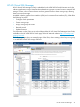
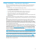
Mappings for the c3000 BladeSystem enclosure:
BladeSystemc-Classinterconnect
bay
ExpansionslotServer typeBladeSystemc-Classenclosuremodel
3/4
2Half height
c3000
2Full height
3
2Full height Double wide
3
4
7
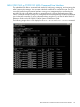
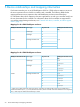
Mappings for the c7000 BladeSystem enclosure:
BladeSystemc-Classinterconnect
bay
ExpansionslotServer typeBladeSystemc-Classenclosuremodel
3/41Half height
c7000
5/6/7/8 *2
3/41Full height
5/6/7/8 *2
5/6/7/83
3/41Full height Double wide
5/6/7/8 *2
5/6/7/83
5/6/7/84
3/45
5/6/7/87
* When using c7000 enclosures and P721m/P731m controllers, the 6Gb SAS BL Switch can be installed only in
c7000 interconnect bays 5, 6, 7, and 8, because the P721m/P731m controller cannot be installed in server expansion
slot 1, which maps to c7000 interconnect bays 3 and 4.
50 Device relationships and mapping information