
9.5.01 HP P4000 SAN Solution User Guide (AX696-96168, February 2012)
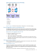
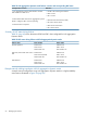
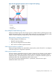
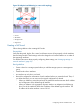


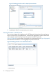

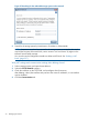

Table 24 Example Adaptive Load Balancing failover scenario and corresponding NIC status
NIC statusExample failover scenario
1. Adaptive Load Balancing bond0 is created.
Motherboard:Port1 and Motherboard:Port2 are both active.
• Bond0 is the master logical interface.
• Motherboard:Port1 is Active.
• Motherboard:Port2 is Active.
2. Motherboard:Port1 interface fails. Because Adaptive
Load Balancing is configured, Motherboard:Port2 continues
operating.
• Motherboard:Port1 status becomes Passive (Failed).
• Motherboard:Port2 status remains Active.
3. Motherboard:Port1 link failure is repaired.
• Motherboard:Port1 resumes Active status.
• Motherboard:Port2 remains Active.
Summary of NIC states during failover
Table 25 (page 64) shows the states of Motherboard:Port1 and Motherboard:Port2 when configured
for Adaptive Load Balancing.
Table 25 NIC status during failover with Adaptive Load Balancing
Status of Motherboard:Port2Status of Motherboard:Port1Failover status
Preferred: NoPreferred: NoNormal Operation
Status: ActiveStatus: Active
Data Transfer: YesData Transfer: Yes
Preferred: NoPreferred: NoMotherboard:Port1 Fails, Data
Transfer Fails Over to
Motherboard:Port2
Status: Active
Data Transfer: Yes
Status: Passive (Failed)
Data Transfer: No
Preferred: NoPreferred: NoMotherboard:Port1 Restored
Status: ActiveStatus: Active
Data Transfer: YesData Transfer: Yes
Example network cabling topologies with Adaptive Load Balancing
A simple network configuration using Adaptive Load Balancing in a high availability environment
is illustrated in Figure 29 (page 65).
64 Managing the network