HP StoreVirtual Storage User Guide Abstract This guide provides instructions for configuring individual storage systems, as well as for creating storage clusters, volumes, snapshots, and remote copies.
© Copyright 2009, 2013 Hewlett-Packard Development Company, L.P. Confidential computer software. Valid license from HP required for possession, use or copying. Consistent with FAR 12.211 and 12.212, Commercial Computer Software, Computer Software Documentation, and Technical Data for Commercial Items are licensed to the U.S. Government under vendor's standard commercial license. The information contained herein is subject to change without notice.
Contents 1 Getting started...........................................................................................7 Creating storage with HP StoreVirtual Storage..............................................................................7 Configuring storage systems.......................................................................................................8 Creating a storage volume using the Management Groups, Clusters, and Volumes wizard.................8 Enabling server access to volumes.
Managing administrative groups..............................................................................................78 Using Active Directory for external authentication........................................................................80 7 Monitoring the SAN.................................................................................83 Monitoring SAN status............................................................................................................
Creating snapshots...............................................................................................................164 Scheduling snapshots............................................................................................................166 Mounting a snapshot............................................................................................................170 Rolling back a volume to a snapshot or clone point..................................................................
21 Replacing hardware..............................................................................251 Replacing disks and rebuilding data.......................................................................................251 Replacing the RAID controller.................................................................................................256 22 LeftHand OS TCP and UDP port usage....................................................263 23 Third-party licenses....................................
1 Getting started HP StoreVirtual Storage enables you to create a virtualized pool of storage resources and manage a SAN. The LeftHand OS software is installed on the HP StoreVirtual Storage and you use the HP StoreVirtual Centralized Management Console (CMC) to manage the storage. For a list of supported software and hardware, see the HP StoreVirtual 4000 Storage Compatibility Matrix at http://www.hp.
7. 8. 9. recommended as the WWNNs based on the management group may change. (See the HP SAN Design Reference Guide.) Create a Fibre Channel server in the CMC. (See “Planning Fibre Channel server connections to management groups” (page 203).) Assign LUNs to the Fibre Channel server. (See “Assigning volumes to Fibre Channel servers” (page 209).) Discover the LUNs in the OS.
Figure 1 The LeftHand OS software storage hierarchy 1. Management group 2. Cluster 3. Volume To complete this wizard, you will need the following information: • A name for the management group.
Using the Map View The Map View tab is available for viewing the relationships between management groups, servers, sites, clusters, volumes and snapshots. When you log in to a management group, there is a Map View tab for each of those elements in the management group. For example, when you want to make changes such as moving a volume to a different cluster, or deleting shared snapshots, the Map View allows you to easily identify how many snapshots and volumes are affected by such changes.
Setting preferences Use the Preferences window to set the following: • Font size in the CMC • Locale for the CMC. The locale determines the language displayed in the CMC. • Naming conventions for storage elements • Online upgrade options. Setting the font size and locale Use the Preferences window, opened from the Help menu, to set font size and locale in the CMC. Font sizes from 9 through 16 are available. The CMC obtains the locale setting from your computer.
If you use the given defaults, the resulting names look like those in Table 2 (page 12). Notice that the volume name carries into all the snapshot elements, including SmartClone volumes, which are created from a snapshot. Table 2 Example of how default names work Element Default name Example SmartClone Volumes VOL_ VOL_VOL_ExchLogs_SS_3_1 Snapshots _SS_ VOL_ExchLogs_SS_1 Remote Snapshots _RS_ VOL_RemoteBackup_RS_1 Schedules to Snapshot a Volume _Sch_SS_ VOL_ExchLogs_Sch_SS_2.
Table 3 CMC setup for remote support Task For more information, see Enable SNMP on each storage system “Enabling SNMP agents” (page 93) Set the SNMP trap recipient to IP address of the system where the remote support client is installed “Adding SNMP traps” (page 94) Open port 8959 (used for the CLI) Your network administrator Set the management group login and password for a read-only (View_Only_Administrator group) user “Adding an administrative user” (page 77) Configuring remote support for HP S
2 Working with storage systems Storage systems displayed in the navigation window have a tree structure of configuration categories under them, as shown in Figure 3 (page 14). The configuration categories provide access to the configuration tasks for individual storage systems. You must configure some basic storage system parameters before using it in a cluster.
Table 4 HP platform identification (continued) HP StoreVirtual model HP platform Documentation Link HP StoreVirtual 4130 HP StoreVirtual 4330 ProLiant DL360p Gen8 HP ProLiant DL360p Gen8 Server Maintenance and Service Guide http://www.hp.com/go/proliantgen8/docs ProLiant DL380p Gen8 HP ProLiant DL380p Gen8 Server User Guide http://www.hp.
1. 2. Select a storage system in the navigation window and log in. Click Storage System Tasks on the Details tab and select Set ID LED On. The ID LED on the front of the storage system is now a bright blue. Another ID LED is located on the back of the storage system. When you click Set ID LED On, the status changes to On. 3. Select Storage System Tasks→Set ID LED Off when you have finished. The LED on the storage system turns off.
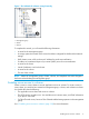
Figure 4 Disk enclosure not found as shown in Details tab When powering off the storage system, be sure to power off the components in the following order: 1. Power off the server blades enclosure or system controller from the CMC as described in “Powering off the storage system” (page 17). 2. Manually power off the disk enclosure. When you reboot the storage system, use the CMC, as described in “Rebooting the storage system” (page 17).
NOTE: If you enter 0 for the value when powering off, you cannot cancel the action. Any value greater than 0 allows you to cancel before the power off actually takes place. 5. Click Power Off. Figure 5 Confirming storage system power off Depending on the configuration of the management group and volumes, your volumes and snapshots can remain available. Upgrading LeftHand OS on storage systems The CMC enables online upgrades for storage systems, including the latest software releases and patches.
Figure 6 Availability tab Checking status of dedicated boot devices Some storage systems contain either one or two dedicated boot devices. In storage systems with two dedicated boot devices, both devices are active by default. If a storage system has dedicated boot devices, the Boot Devices tab appears in the Storage configuration category. Storage systems that do not have dedicated boot devices will not display the Boot Devices tab.
Table 5 Boot device status (continued) Boot device status Description Not Recognized The device is not recognized as a boot device. Unsupported The device cannot be used. (For example, the compact flash card is the wrong size or type.) NOTE: When the status of a boot device changes, an event is generated. See “Alarms and events overview” (page 85). Replacing a dedicated boot device If a boot hard drive fails, you will see an event that the boot device is faulty.
3 Configuring RAID and Managing Disks For each storage system, you can select the RAID configuration and the RAID rebuild options, and monitor the RAID status. You can also review disk information and, for some models, manage individual disks. Getting there 1. 2. In the navigation window, select a storage system and log in if necessary. Open the tree under the storage system and select the Storage category.
Table 6 Descriptions of RAID levels (continued) RAID level Description data. RAID 1+0 first mirrors each drive in the array to another, and then stripes the data across the mirrored pair. If a physical drive fails, the mirror drive provides a backup copy of the files and normal system operations are not interrupted. RAID 1+0 can withstand multiple simultaneous drive failures, as long as the failed drives are not mirrored to each other.
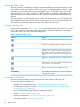
Table 7 Information in the RAID setup report This item Describes this Device Name The disk sets used in RAID. The number and names of devices varies by storage system and RAID level. Device Type The RAID level of the device. For example, in a HP P4300 G2, RAID 5 displays a Device Type of RAID 5 and subdevices as 8. NOTE: On the 4730 and the 4630 with 25 drives, since the global hot spare is configured, each logical drive will show 13 subdevices (12 data drives plus 1 spare).
Using Network RAID in a cluster A cluster is a group of storage systems across which data can be protected by using Network RAID. Network RAID protects against the failure of a RAID disk set within a storage system, failure of an entire storage system or external failures like networking or power. For example, if an entire storage system in a cluster becomes unavailable, data reads and writes continue because the missing data can be obtained from the other storage systems.
Table 8 Data availability and safety in RAID configurations (continued) Configuration Data safety and availability during disk failure Data availability if an entire individual storage system fails or if network connection to a storage system is lost Volumes configured with Network RAID-10 or greater on clustered storage systems , RAID 6 Yes. 2 disks per RAID set can fail Yes without copying from another storage system in the cluster.
Reconfiguring RAID Reconfiguring RAID on a storage system or a StoreVirtual VSA destroys any data stored on that storage system. For VSAs, there is no alternate RAID choice, so the only outcome for reconfiguring RAID is to wipe out all data. • Changing preconfigured RAID on a new storage system RAID must be configured on individual storage systems before they are added to a management group.
Reconfiguring tiers Reconfigure tiers if you have added a disk or if the tiers are configured incorrectly. IMPORTANT: If the StoreVirtual VSA is in a management group, reconfiguring tiers causes the store to restart. If any volumes are configured with Network RAID-0, a message opens warning that those volumes will go offline and you should log off before continuing. 1. 2. 3. Using the CMC, navigate to the RAID Setup tab of the StoreVirtual VSA. Click RAID Setup Tasks and select Reconfigure Tiers.
The RAID status is located at the top of the RAID Setup tab in Storage. RAID status also appears in the Details tab on the main CMC window when a storage system is selected in the navigation window. Figure 10 Monitoring RAID status on the main CMC window 1. RAID status The status displays one of five RAID states. • Normal—RAID is synchronized and running. No action is required. • Rebuilding—A new disk has been inserted in a drive bay, or a hot spare has been activated, and RAID is currently rebuilding.
Figure 11 Example of columns in the Disk Setup tab 1. Activated Drive ID LEDs Table 10 Description of items on the disk report Column Description Disk Corresponds to the physical slot or bay in the storage system. This column also displays the Drive ID LED if it has been activated. Status Status is one of the following: • Active—green (on and participating in RAID) • Active, Un-authorized—yellow (the controller detects a communication problem with the drive, and cannot control the drive LEDs.
Table 10 Description of items on the disk report (continued) Column Description • Worn out—Red; drive is at 0% of remaining estimated life • Failed—Red; drive has failed and writes are not permitted Capacity The data storage capacity of the disk. SSD drives and wear life The wear life statistics for SSD drives report drive usage so that drives can be replaced before they wear out. Wear life statistics are displayed on the Disk Setup tab.
Fixing a Foreign disk • • To use the disk, you can perform any of the following actions to remove the Foreign status and make the storage available: ◦ Reconfigure RAID from the RAID Setup Tasks menu. ◦ Add the disk to RAID on the Disk Setup Tasks menu. ◦ Manually delete partitions from the disk using the hypervisor.
Figure 14 Viewing the Disk Setup tab in a HP P4500 G2 Figure 15 Diagram of the drive bays in a HP P4500 G2 Viewing disk status for the HP P4300 G2 The disks are labeled 1 through 8 in the Disk Setup window, shown in Figure 16 (page 32), and correspond to the disk drives from top to bottom, left to right (Figure 17 (page 33)), when you are looking at the front of the HP P4300 G2.
Figure 17 Diagram of the drive bays in a HP P4300 G2 Viewing disk status for the P4800 G2 The disks are labeled 1 through 35 in the Disk Setup window ( Figure 18 (page 33)), and correspond to the disk drives from top to bottom, left to right, (Figure 19 (page 33)), when you are looking at the front of the P4800 G2. For the P4800 G2, the columns Health and Safe to Remove help you assess the health of a disk and tell you whether or not you can replace it without losing data.
For the P4900 G2, the columns Health and Safe to Remove help you assess the health of a disk and tell you whether or not you can replace it without losing data.
Figure 22 Viewing the Disk Setup tab in a HP StoreVirtual 4130 Figure 23 Diagram of the drive bays in a HP StoreVirtual 4130 Viewing disk status for the HP StoreVirtual 4330 The disks are labeled 1 through 8 in the Disk Setup window (Figure 24 (page 36)), and correspond to the disk drives from top to bottom, left to right (Figure 25 (page 36)), when you are looking at the front of the HP StoreVirtual 4330.
Figure 24 Viewing the Disk Setup tab in an HP StoreVirtual 4330 Figure 25 Diagram of the drive bays in an HP StoreVirtual 4330 Viewing the disk status for the HP StoreVirtual 4530 The disks are labeled 1 through 12 in the Disk Setup window (Figure 26 (page 37)), and correspond to the disk drives from top to bottom, left to right (Figure 27 (page 37)), when you are looking at the front of the HP StoreVirtual 4530.
Figure 26 Viewing the Disk Setup tab in an HP StoreVirtual 4530 Figure 27 Diagram of the drive bays in an HP StoreVirtual 4530 Viewing the disk status for the HP StoreVirtual 4630 The disks are labeled 1 through 25 in the Disk Setup window (Figure 28 (page 38)), and correspond to the disk drives from top to bottom, left to right (Figure 29 (page 38)), when you are looking at the front of the HP StoreVirtual 4630. Note the hot spare status of disk number 25.
Figure 28 Viewing the Disk Setup tab in an HP StoreVirtual 4630 Figure 29 Diagram of the drive bays in an HP StoreVirtual 4630 Viewing the disk status for the HP StoreVirtual 4730 The disks are labeled 1 through 25 in the Disk Setup window (Figure 30 (page 39)), and correspond to the disk drives from top to bottom, left to right (Figure 31 (page 39)), when you are looking at the front of the HP StoreVirtual 4730. Note the hot spare status of disk number 25.
Figure 30 Viewing the Disk Setup tab in an HP StoreVirtual 4730 Figure 31 Diagram of the drive bays in an HP StoreVirtual 4730 Viewing the disk status for the HP StoreVirtual 4335 The disks are labeled 1 through 10 in the Disk Setup window (Figure 32 (page 40)) and correspond to the disk drives from top to bottom, left to right (Figure 33 (page 40)) when you are looking at the front of the HP StoreVirtual 4335.
Figure 32 Viewing the Disk Setup tab in a HP StoreVirtual 4335 Figure 33 Diagram of the drive bays in a HP StoreVirtual 4335 1. The SSD drives must be installed in drive bays 8, 9, and 10. Adding disks to RAID Extend the StoreVirtual VSA capacity by adding virtual disks. With the appropriate licensing, the StoreVirtual VSA can also be configured for Adaptive Optimization with storage tiers by adding the appropriate disks in the hypervisor and then configuring tiers when adding the disks to RAID.
Replacing a disk The correct procedure for replacing a disk in a storage system depends upon a number of factors, including the RAID configuration, the data protection level of volumes and snapshots, and the number of disks being replaced. Replacing a disk in a storage system that is in a cluster requires rebuilding data on the replaced disk. Replacing a disk in a storage system includes the following basic steps.
Replacing disks in hot-swap storage systems In hot-swap storage systems configured with RAID 1+0, RAID 5, or RAID 6, a faulty or failed disk can be removed and replaced with a new one. RAID will rebuild and the drive will return to Normal status. CAUTION: Before replacing a drive in a hot-swap storage system, always check the Safe to Remove status in the CMC Disk Setup tab to verify that the drive can be removed without causing RAID to go Off.
Table 12 Drive LEDs, status and definitions (continued) Item LED Status Definition Flashing amber/green The drive is a member of one or more logical drives and predicts the drive will fail. Flashing amber The drive is not configured and predicts the drive will fail. Solid amber The drive has failed. Off The drive is not configured by a RAID controller. When RAID is Normal in RAID 1+0, RAID 5, or RAID 6, all drives indicate they are safe to remove.
• All volumes and snapshots show a status of Normal. • Any volumes or snapshots that were being deleted have completed deletion. • One of the following: ◦ RAID status is Normal ◦ If RAID is Rebuilding or Degraded, for storage systems that support hot-swapping of drives, the Safe to Remove column indicates Yes (the drive can safely be replaced).
Figure 35 RAID rebuilding on the RAID Setup tab Figure 36 Disk rebuilding on the Disk Setup tab Troubleshooting Disk drive carrier with older firmware is not detected and drive status is displayed inconsistently in different tools If a disk drive carrier is running an older firmware version that the RAID controller in the storage system does not detect, the controller incorrectly reports the drive as unauthorized and does not turn on the LEDs.
4 Managing the network Correctly setting up the network for HP StoreVirtual Storage ensures data availability and reliability. IMPORTANT: The network settings must be the same for the switches, clients, and storage systems. Set up the end-to-end network before creating storage volumes. Network best practices • Isolate the SAN, including CMC traffic, on a separate network. If the SAN must run on a public network, use a VPN to secure data and CMC traffic.
be the management interface. Configuring two default gateways will result in communication problems in the cluster. • When configuring a management interface on an HP StoreVirtual Storage system, you must designate the storage interface as the LeftHand OS interface for that storage system in the CMC. This is done on the Communications tab in the Network configuration category for that storage system.
Table 13 Network interface status and information (continued) Column Description • BladeBoard:Port1 • FlexLOM:Port1 • NICSlot:Port1 • bond0—The bonded interface(s) (appears only if storage system is configured for bonding) Description Describes each interface listed. For example, the bond0 is the Logical Failover Device. Speed/Method Lists the actual operating speed reported by the interface. Duplex/Method Lists duplex as reported by the interface. Status Describes the state of the interface.
To change the speed and duplex 1. 2. 3. 4. 5. 6. 7. In the navigation window, select the storage system and log in. Open the tree, and select Network. Click the TCP Status tab. Select the interface to edit. Click TCP Status Tasks, and select Edit. Select the combination of speed and duplex that you want. Click OK. A series of status messages appears. Then the changed setting appears in the TCP status report. NOTE: You can also use the Configuration Interface to edit the speed and duplex.
configure jumbo frames on each client and each network switch may result in data unavailability or performance degradation. Jumbo frames can co-exist with 1500 byte frames on the same subnet if the following conditions are met: • Every device downstream of the storage system on the subnet must support jumbo frames. • If you are using 802.1q virtual LANs, jumbo frames and nonjumbo frames must be segregated into separate VLANs.
6. 7. 8. Change the flow control setting on the Edit window. Click OK. Repeat these steps for all the NICs you want to change. On the TCP Status tab window, for bonded NICs, the NIC flow control column shows the flow control settings for the physical NICs, and the bond0 as blank. Flow control is enabled and working in this case The TCP/IP tab Lists the network interfaces on the storage system.
3. 4. Click TCP/IP Tasks, and select Ping. Select which network interface to ping from, if you have more than one enabled. A bonded interface has only one interface from which to ping. 5. Enter the IP address to ping, and click Ping. If the server is available, the ping is returned in the Ping Results window. If the server is not available, the ping fails in the Ping Results window. Configuring the IP address manually Use 1. 2. 3. 4. 5. 6. 7. 8.
fault tolerance, load balancing and/or bandwidth aggregation for the network interface cards in the storage system. Bonds are created by joining physical NICs into a single logical interface. This logical interface acts as the master interface, controlling and monitoring the physical slave interfaces. Bonding two interfaces for failover provides fault tolerance at the local hardware level for network communication.
category, TCP/IP tab window. Table 16 (page 54) lists the names of these interfaces. These interfaces can be bonded a number of ways. Note that not all the bond configurations which are supported by HP StoreVirtual Storage are supported with 10 GbE NICs. NOTE: For the HP StoreVirtual 4630, the CMC shows an additional two NICS available for the management network.
Table 17 Supported bonding configurations (continued) Number of ports x NIC type Active-Passive 802.3ad ALB 2 x 1 GbE Yes Yes Yes 3 x 1 GbE No Yes Yes 4 x 1 GbE No Yes Yes 2 x 10 GbE Yes Yes Yes 1 x 1 GbE + 1 x 10 GbE in single bond Yes No No Multiple bonds of same type1 Yes Yes Yes Multiple bonds of different type2 Yes Yes Yes No No Yes HP StoreVirtual 4630 storage systems 2 x 10 GbE 1 Both bonded interfaces are the same type.
How Active-Passive bonding works Bonding NICs for Active-Passive allows you to specify a preferred interface that will be used for data transfer. This is the active interface. The other interface acts as a backup, and its status is “Passive (Ready).” Physical and logical interfaces The two NICs in the storage system are labeled as listed in Table 19 (page 56). If both interfaces are bonded for failover, the logical interface is labeled bond0 and acts as the master interface.
Which physical interface is preferred When the Active-Passive bond is created, if both NICs are plugged in, the LeftHand OS interface becomes the active interface. The other interface is Passive (Ready). For example, if N:Port1 is the preferred interface, it will be active and N:Port2 will be Passive (Ready). Then, if N:Port1 fails, N:Port2 changes from Passive (Ready) to active. Interface:Port1 changes to Passive (Failed).
Figure 37 Active-Passive in a two-switch topology with server failover 1. Servers 2. HP StoreVirtual Storage systems 3. Storage cluster 4. GigE trunk 5. Active path 6. Passive path The two-switch scenario in Figure 37 (page 58) is a basic, yet effective, method for ensuring high availability. If either switch fails, or a cable or NIC on one of the storage systems fails, the Active-Passive bond causes the secondary connection to become active and take over.
Figure 38 Active-Passive failover in a four-switch topology 1. Servers 2. HP StoreVirtual Storage systems 3. Storage cluster 4. GigE trunk 5. Active path 6. Passive path Figure 38 (page 59) illustrates the Active-Passive configuration in a four-switch topology. How link aggregation dynamic mode bonding works Link Aggregation Dynamic Mode allows the storage system to use both interfaces simultaneously for data transfer. Both interfaces have an active status.
Table 23 Link aggregation dynamic mode failover scenario and corresponding NIC status Example failover scenario NIC status 1. Link Aggregation Dynamic Mode bond0 is created. Interface:Port1 and Interface:Port2 are both active. • Bond0 is the master logical interface. • Interface:Port1 is Active. • Interface:Port2 is Active. 2. Interface:Port1 interface fails. Because Link Aggregation • Interface:Port1 status becomes Passive (Failed).
Figure 39 Link aggregation dynamic mode in a single-switch topology 1. Servers 2. HP StoreVirtual Storage systems 3. Storage cluster How Adaptive Load Balancing works Adaptive Load Balancing allows the storage system to use both interfaces simultaneously for data transfer. Both interfaces have an active status. If the interface link to one NIC goes offline, the other interface continues operating. Using both NICs also increases network bandwidth.
Table 25 Example Adaptive Load Balancing failover scenario and corresponding NIC status Example failover scenario NIC status 1. Adaptive Load Balancing bond0 is created. Interface:Port1 and Interface:Port2 are both active. • Bond0 is the master logical interface. • Interface:Port1 is Active. • Interface:Port2 is Active. 2. Interface:Port1 interface fails. Because Adaptive Load Balancing is configured, Interface:Port2 continues operating. • Interface:Port1 status becomes Passive (Failed). 3.
Figure 40 Adaptive Load Balancing in a two-switch topology 1. Servers 2. HP StoreVirtual Storage systems 3. Storage cluster 4. GigE trunk Creating a NIC bond IMPORTANT: You cannot bond the virtual NICs in a StoreVirtual VSA. Follow these guidelines when creating NIC bonds: Prerequisites Verify that the speed, duplex, flow control, and frame size are all set properly on both interfaces that are being bonded.
• Ensure that the bond has a static IP address for the logical bond interface. The default values for the IP address, subnet mask and default gateway are those of one of the physical interfaces. • Verify on the Communication tab that the LeftHand OS interface is communicating with the bonded interface. CAUTION: To ensure that the bond works correctly, you should configure it as follows: • Create the bond on the storage system before you add it to a management group.
NOTE: Because it can take a few minutes for the storage system to set the network address, the search may fail the first time. If the search fails, wait a minute or two and select Try Again on the Network Search Failed message. 12. Verify the new bond interface. Figure 42 Viewing a new Active-Passive bond 1. Bonded logical network interface 2. Physical interfaces shown as slaves The bond interface shows as “bond0” and has a static IP address. The two physical NICs now show as slaves in the Mode column.
Figure 44 (page 66) shows the status of interfaces in an Active-Passive bond. Figure 45 (page 66) shows the status of interfaces in a Link Aggregation Dynamic Mode bond. Figure 44 Viewing the status of an Active-Passive bond 1. Preferred interface Figure 45 Viewing the status of a link aggregation dynamic mode bond 1.
Deleting a NIC bond When you delete an Active-Passive bond, the preferred interface assumes the IP address and configuration of the deleted logical interface. The other NIC is disabled, and its IP address is set to 0.0.0.0. When you delete either a Link Aggregation Dynamic Mode or an Adaptive Load Balancing bond, one of the active interfaces in the bond retains the IP address of the deleted logical interface. The other NIC is disabled, and its IP address is set to 0.0.0.0. 1.
Figure 47 Verifying interface used for LeftHand OS communication 5. Verify that the LeftHand OS communication port is correct. Table 27 Troubleshooting NIC bonding Issue Description In rare situations, creating a bond may result in an event notice Due to timing issues in the software, after you create a new bond, the event notice NIC Motherboard:Port2=down may appear. You can safely ignore this event.
6. Click OK. A confirmation message opens. If you are disabling the only interface, the message warns that the storage system may be inaccessible if you continue. 7. Click OK. If the storage system for which you are disabling the interface is a manager in a management group, a window opens which displays all the IP addresses of the managers in the management group and a reminder to reconfigure the application servers that are affected by the update.
1. 2. 3. 4. 5. On the management group DNS tab, select the server to edit. Click DNS Tasks and select Edit DNS Servers Make the desired changes to the DNS servers in the list. Click OK. Use the arrows on the Edit DNS Servers window to order the servers. The servers will be accessed in the order they appear in the list. 6. Click OK when you are finished. Adding or changing domain names to the DNS suffix list Add up to six domain names to the DNS suffix list (also known as the look-up zone).
3. 4. 5. 6. 7. 8. Click the Routing tab. On the Routing tab, select the optional route to change. Click Routing Tasks, and select Edit Routing Information. Select a Route, and click Edit. Change the relevant information. Click OK to finish. Deleting routing information You 1. 2. 3. 4. 5. 6. 7. 8. can only delete user-added routes. In the navigation window, select a storage system, and log in. Open the tree, and select Network. Click the Routing tab.
Figure 48 Selecting the LeftHand OS network interface and updating the list of managers 4. 5. 6. 7. Select an IP address from the list of manager IP addresses. Click Communication Tasks, and select Select LeftHand OS Interface. Select an Ethernet port for this address. Click OK. The storage system connects to the IP address through the selected Ethernet port.
Figure 49 Viewing the list of manager IP addresses 4. Click Communication Tasks, and select Update Communications List. The list is updated with the current storage system in the management group and a list of IPs with every manager’s enabled network interfaces. A window opens which displays the manager IP addresses in the management group and a reminder to reconfigure the application servers that are affected by the update.
5 Setting the date and time The storage systems within management groups use the date and time settings to create a time stamp when data is stored. You set the time zone and the date and time in the management group, and the storage systems inherit those management group settings. • Using network time protocol Configure the storage system to use a time service, either external or internal to your network. • Setting the time zone Set the time zone for the storage system.
NOTE: When using a Windows server as an external time source for an storage system, you must configure W32Time (the Windows Time service) to also use an external time source. The storage system does not recognize the Windows server as an NTP server if W32Time is configured to use an internal hardware clock. 1. Click Time Tasks, and select Add NTP Server. 2. Enter the IP address of the NTP server you want to use. 3. Decide whether you want this NTP server to be designated preferred or not preferred.
The server you added first is the one accessed first when time needs to be established. If this NTP server is not available for some reason, the next NTP server that was added, and is preferred, is used for time serving. To change the order of access for time servers 1. Delete the server whose place in the list you want to change. 2. Add that same server back into the list. It is placed at the bottom of the list, and is the last to be accessed.
6 Managing authentication Manage authentication to the HP StoreVirtual Storage using administrative users and groups. Managing administrative users When you create a management group, one default administrative user is created. The default user automatically becomes a member of the Full Administrator group. Use the default user and/or create new ones to provide access to the management functions of the LeftHand OS software. Adding an administrative user 1. 2. 3. 4. 5. 6. 7. 8.
4. 5. 6. In the Member Groups section, select the group from which to remove the user. Click Remove. Click OK to finish. Deleting an administrative user 1. 2. 3. 4. Log in to the management group, and select the Administration category. Select a user in the Users table. Click Administration Tasks in the tab window, and select Delete User. Click OK. NOTE: If you delete an administrative user, that user is automatically removed from any administrative groups.
Adding administrative groups When you create a group, you also set the permission level for the users assigned to that group. 1. Log in to the management group, and select the Administration category. 2. Click Administration Tasks in the tab window, and select New Group. 3. Enter a group name and an optional description. 4. Select the permission level for each management function for the group you are creating. See Table 29 (page 78) for more information. 5. To add a user to the group: a.
3. 4. Click OK on the confirmation window. Click OK to finish. Using Active Directory for external authentication Use Active Directory to simplify management of user authentication with HP StoreVirtual Storage. Configuring Active Directory allows Microsoft Windows domain users to authenticate to HP StoreVirtual Storage using their Windows credentials, avoiding the necessity of adding and maintaining individual users in the LeftHand OS software.
Best practices • Create a unique group in the CMC for the Active Directory association. Use a name and description that signifies the Active Directory association. See “Adding administrative groups” (page 79). • Create a separate LeftHand OS ‘administrator’ group in Active Directory. • Create a unique user in Active Directory to use as the Bind user for the management group to allow for communication between storage and Active Directory.
a. b. c. 5. 6. Click Find External Group. Enter the user name in the Enter AD User Name box and click OK. Select the correct group from the list that opens of Active Directory Groups and click OK. Click OK when you have finished editing the group. Log out of the management group and log back in using your UPN login (e.g., name@company.com) to verify the configuration.
7 Monitoring the SAN Monitor the SAN to: • Track usage. • Ensure that best practices are followed when changes are made, such as adding additional storage systems to clusters. • Maintain the overall health of the SAN. Tools for monitoring the SAN include the SAN Status Page, the Configuration Summary and the Best Practice table, the Alarms and Events features, including customized notification methods, and diagnostic tests and log files available for the storage systems.
The best practices displayed in this content pane are the same as those displayed on the Configuration Summary page. • Configuration Summary—Monitor SAN configurations to ensure optimum capacity management, performance, availability, and ease of management. • Volume Data Protection Level—Ensure that the SAN is configured for ongoing maximum data protection while scaling capacity and performing system maintenance.
Customizing the SAN Status Page layout Customize the layout of the SAN Status Page to highlight the information most important to you. All customizations are retained when the CMC is closed and restarted. Drag-and-drop content panes to change their position on the page. The layout is three columns by default. To rearrange content panes, drag a content pane and drop it on another content pane. The two panes switch places.
require taking action and are available only from the Events window for each management group. • Warning—Provides important information about a system component that may require taking action. These types of events are visible in both the Alarms window (for all management groups) and the Events window (for the management group where the alarm occurred). • Critical—Provides vital information about a system component that requires user action.
NOTE: Except for the P4800 G2, alarms and events information is not available for storage systems listed under Available Systems in the CMC, because they are not currently in use on the SAN. Table 32 (page 87) defines the alarms and events columns that appear in the CMC. Table 32 Alarms and events column descriptions Column Description Severity Severity of the event or alarm: informational, warning, or critical. Date/Time Date and time the event or alarm occurred.
Viewing and copying alarm details 1. 2. 3. In the navigation window, log in to the management group. In the Alarms window, double-click an alarm. For assistance with resolving the alarm, click the link in either the Event field or the Resolution field. The link opens to a database that contains advisories and documents that may have additional information about the event and how to resolve it. If no results are found, no advisories that directly apply to that event have been published yet. 4. 5. 6.
You must also configure the destination computer to receive the log files by configuring syslog on the destination computer. The syslog facility to use is local5, and the syslog levels are LOG_INFO, LOG_WARNING, LOG_CRIT. See the syslog documentation for that computer for information about configuring syslog. To set up remote log destinations: 1. In the navigation window, log in to the management group. 2. Select Events in the tree. 3. Click Event Tasks, and select Edit Remote Log Destinations. 4.
To change the date range: 1. In the From list, select Choose From, and select the date. 2. Click OK. 3. In the To list, select Choose To, and select the date. 4. Click OK. 5. Click Update. Combine these date range filters with the options available in the filters panel described below. To use the filters panel: 1. 2. In the Events window, open the filters panel by clicking the expand button below the toolbar). Use the filter lists to narrow the list of events.
Copying events to the clipboard 1. 2. 3. In the navigation window, log in to the management group. Select Events in the tree. Do one of the following: • Select one or more events, click Event Tasks, and select Copy Selected to Clipboard. • Click Event Tasks, and select Copy All to Clipboard. Exporting event data to a .csv or .txt file 1. 2. 3. 4. In the navigation window, log in to the management group. Select Events in the tree. Click Event Tasks, and select Export Events.
6. In the Sender Address field, enter the email address, including the domain name, to use as the sender for notifications. The system automatically adds the host name of the storage system in the email From field, which appears in many email systems. This host name helps identify where the event occurred. 7. Do one of the following: • To save your changes and close the window, click Apply. • To save your changes, close the window, and send a test email message, click Apply and Test.
community string must be set to public. To receive notification of events, you must configure SNMP traps. If using the HP System Management Homepage, view the SNMP settings there. You can also start SNMP and send test v1 traps. Enabling SNMP agents Most storage systems allow enabling and disabling SNMP agents. After installing version 9.0, SNMP will be enabled on the storage system by default.
For HP remote support, add the Central Management Server for HP Insight Remote Support. 5. Do one of the following: • Select By Address and enter the IP address, then select an IP Netmask from the list. Select Single Host if adding only one SNMP client. After entering the information, the dialog box displays acceptable and unacceptable combinations of IP addresses and IP netmasks so you can correct issues immediately. • Select By Name and enter a host name.
1. 2. 3. 4. In the navigation window, log in to the management group. In the tree, select Events→SNMP. Click SNMP Tasks and select Edit SNMP Traps Settings. Enter the Trap Community String. The trap community string does not have to be the same as the community string used for access control, but it can be. 5. 6. Click Add. Enter the IP address or host name for the SNMP client that is receiving the traps. For HP remote support, add the CMS for HP Insight Remote Support. 7. Select the Trap Version.
6. 7. Clear the selected severities checkboxes. Click OK to confirm. Using the SNMP MIBs The SNMP MIBs provide read-only access to the storage system. The SNMP implementation in the storage system supports MIB-II compliant objects. These files, when loaded in the SNMP client, allow you to see storage system-specific information such as model number, serial number, hard disk capacity, network characteristics, RAID configuration, DNS server configuration details, and more. NOTE: With version 8.
• NETWORK-SERVICES-MIB • NOTIFICATION-LOG-MIB • RFC1213-MIB • SNMP-TARGET-MIB • SNMP-VIEW-BASED-ACM-MIB • SNMPv2-MIB • UCD-DLMOD-MIB • UCD-SNMP-MIB Troubleshooting SNMP Table 33 SNMP troubleshooting Issue Solution SNMP queries are timing out Ensure that the timeout value is long enough for your environment. In complex configurations, SNMP queries should have longer timeouts. SNMP data gathering is not instantaneous, and scales in time with the complexity of the configuration.
NOTE: Available diagnostic tests depend on the storage system. For VSA, only the Disk Status Test is available. Table 34 Example list of hardware diagnostic tests and pass/fail criteria Diagnostic test Description Pass criteria Fail criteria Fan Test Checks the status of all fans. Fan is normal Fan is faulty or missing Power Test Checks the status of all power supplies. Supply is normal Supply is faulty or missing Temperature Test Checks the status of all temperature sensors.
Figure 52 Viewing the hardware information for a storage system Saving a hardware information report 1. 2. 3. Click Hardware Information Tasks and select Save to File to download a text file of the reported statistics. Choose the location and name for the report. Click Save. The report is saved with an .html extension. Hardware information report details Available hardware report statistics vary depending on the storage system.
Table 35 Selected details of the hardware report (continued) Item Definition • Driver name • Driver version DNS data Information about DNS, if a DNS server is being used, providing the IP address of the DNS servers. IP address of the DNS servers. Memory Information about RAM in the storage system, including values for total memory and free memory in GB. CPU Details about the CPU, including model name or manufacturer of the CPU, clock speed of the CPU, and cache size. Stat Information about the CPU.
The Log Files tab lists two types of logs: • Log files that are stored locally on the storage system (displayed on the left side of the tab). • Log files that are written to a remote log server (displayed on the right side of the tab). This list is empty until you configure remote log files and the remote log target computer. Saving log files locally 1. 2. 3. 4. 5. Select a storage system in the navigation window. Open the tree below the storage system and select Diagnostics. Select the Log Files tab.
4. 5. 6. 7. Select the log in the Remote logs list. Click Log File Tasks and select Edit Remote Log Destination. Change the log type or destination and click OK. Ensure that the remote computer has the proper syslog configuration. Deleting remote logs 1. 2. 3. 4. 5. Select a storage system in the navigation window. Open the tree below the storage system and select Diagnostics. Select the Log Files tab. Click Log File Tasks and select Delete Remote Log Destination. Click OK to confirm.
• Network information, “Managing the network” (page 46) • RAID information, “Configuring RAID and Managing Disks” (page 21) To export the summary: 1. From the CMC menu bar, select Tasks→System Summary. 2. Click Export. 3. Select a location for the file, and rename it if desired. 4. Click Export.
8 Working with management groups A management group is a collection of one or more storage systems. It is the container within which you cluster storage systems and create volumes for storage. Creating a management group is the first step in creating HP StoreVirtual Storage. Functions of management groups • Provide the highest administrative domain for the SAN. Typically, storage administrators will configure at least one management group within their data center.
Table 36 Management group components (continued) Component Description Type of cluster A cluster can be standard or Multi-Site. For a Multi-Site configuration, ensure the physical sites and the storage systems at each site are already created. Virtual IP addresses (VIPs) Plan a unique VIP for each cluster. VIPs ensure fault-tolerant server access to the cluster and enable iSCSI load balancing.
Set management group time 1. Select the method by which to set the management group time: • [Recommended] To use an NTP server, enter the server DNS name or IP address. NOTE: group. • 2. If you enter a name, DNS must be configured on the storage systems in the To set the time manually, select Edit to display the Date and Time Configuration window. Check each field on this window to set the time for all storage systems in this management group. Click Next. Set DNS server 1. 2.
When the management group is created, check the Best Practice Summary to verify that the configuration is following best practices for availability and data protection. See “Best Practice summary overview” (page 109). Logging in to a management group You must manually log in to a management group. After you have logged in to one management group, the CMC attempts to use the credentials from the first login when you log in to additional management groups.
maximum for storage systems than the 43 iSCSI sessions are to the maximum recommended iSCSI sessions for a management group. Figure 54 Summary graph 1. The items in the management group are all within optimum limits. The display is proportional to the optimum limits. Configuration warnings When any item nears a recommended maximum, it turns orange, and remains orange until the number is reduced to the optimal range. See Figure 55 (page 108).
Configuration guidance The optimal and recommended number of storage items in a management group depend largely on the network environment, the configuration of the SAN, the applications accessing the volumes, and how you are using snapshots. However, the Configuration Summary can provide some broad guidelines that help you manage the SAN to obtain the best and safest performance and scalability for your circumstances.
Figure 57 Best Practice Summary for well-configured SAN Expand the management group in the summary to see the individual categories that have recommended best practices. The summary displays the status of each category and identifies any conditions that fall outside the best practice. Click on a row to see details about that item's best practice. Disk level data protection Disk level data protection indicates whether the storage system has an appropriate disk RAID level set.
Volume-level data protection Use a data protection level greater than Network RAID-0 to ensure optimum data availability if a storage system fails. For information about data protection, see “Planning data protection” (page 142). Volume access Use iSCSI load balancing to ensure better performance and better utilization of cluster resources. For more information about iSCSI load balancing, see “iSCSI load balancing” (page 241).
1. 2. In the navigation window, select a management group and log in by any of the following methods: • Double-click the management group. • Open the Management Group Tasks menu, and select Log in to Management Group. You can also open this menu by right-clicking on the management group. • Click any of the Log in to view links on the Details tab. Enter the user name and password, and click Log In.
Stopping managers Under normal circumstances, you stop a manager when you are removing a storage system from a management group. Stopping a manager that will compromise fault tolerance generates an alarm. You cannot stop the last manager in a management group. The only way to stop the last manager is to delete the management group, which permanently deletes all data stored on volumes in the management group. Implications of stopping managers • Quorum of the storage systems may be decreased.
Saving the management group configuration information 1. 2. 3. From the Tasks menu, select Management Group→View Management Group Configuration. If there are multiple management groups, select the management group from the List of Management Groups and click Continue. Click Save in the Management Group Configuration window to save the configuration details in a .txt file. Shutting down a management group Safely shut down a management group to ensure the safety of your data.
1. 2. Stop server or host access to the volumes in the list. Click Shut Down Group. Restarting the management group When you are ready to restart the management group, simply power on the storage systems for that group: 1. Power on the storage systems that were shut down. 2. Click Find→Find Systems in the CMC to discover the storage systems. When the storage systems are all operating properly, the volumes become available and can be reconnected with the hosts or servers.
Figure 59 Manually setting management group to normal mode 3. Click Set To Normal. Removing a storage system from a management group When a storage system needs to be repaired or upgraded, remove it from the management group before beginning the repair or upgrade. Also remove a storage system from a management group if you are replacing it with another system. Prerequisites • Stop the manager on the storage system if it is running a manager.
Prerequisites • Log in to the management group. • Remove all volumes and snapshots. • 1. 2. 3. Delete all clusters. In the navigation window, log in to the management group. Click Management Group Tasks on the Details tab, and select Delete Management Group. In the Delete Management Window, enter the management group name, and click OK. After the management group is deleted, the storage systems return to the Available Systems pool.
9 Working with managers and quorum When a management group is created using release 10.0, it will be created with the correct number of managers started. Older management groups upgraded to release 10.0 may require additional managers or a Failover Manager started before the upgrade to 10.0 can be completed. See Table 41 (page 119) to see the optimum number of managers required for each configuration.
For more information about managers, see “Managers overview” (page 118). Table 41 Default number of managers added when a management group is created Number of storage systems Manager configuration 1 1 manager 2 2 managers and a virtual manager, if a Failover Manager is not available. 3 3 managers 4 3 managers 5 or more 5 managers 1 2 1 2 See “Failover Managers” (page 120) and “Virtual Managers” (page 120) for more information about virtual managers and Failover Managers.
Failover Managers The Failover Manager is a specialized version of the LeftHand OS software designed to operate as a manager and provide automated failover capability. It runs as a virtual appliance in either a VMware vSphere or Microsoft Hyper-V Server environment, and must be installed on network hardware other than the storage systems in the SAN. The Failover Manager participates in the management group as a manager; however, it performs quorum operations only, not data movement operations.
Figure 61 Virtual manager added to a management group Using the Failover Manager Adding a Failover Manager to the management group enables the SAN to have automated failover using a manager installed on network hardware other than the storage systems in the HP StoreVirtual Storage. Once installed and configured on network hardware, the Failover Manager is added to a management group where it serves solely as a quorum tie-breaking manager.
The installer for the Failover Manager for Hyper-V Server includes a wizard that guides you through configuring the virtual machine on the network and powering on the Failover Manager. CAUTION: Do not install the Failover Manager on a volume that is served from HP StoreVirtual Storage, since this would defeat the purpose of the Failover Manager.
Using the Failover Manager for VMware vSphere Install the Failover Manager from the DVD, or from the DVD .iso image downloaded from the website: http://www.hp.com/go/StoreVirtualDownloads The installer offers two choices for installing the Failover Manager for VMware: • Failover Manager for VMware vSphere—The installer for the Failover Manager for VMware vSphere includes a wizard that guides you through configuring the virtual machine on the network and powering on the Failover Manager.
14. If this is the only Failover manager you are installing, select No, I am done and click Next. NOTE: If you want to install another Failover Manager, the wizard repeats the steps, using information you already entered, as appropriate. 15. Finish the installation, reviewing the configuration summary, and click Deploy. When the installer is finished, the Failover Manager is ready to be used in the HP StoreVirtual Storage.
Installing the Failover Manager using the OVF files with the VI Client 1. Download the .OVF files from the following website: http://www.hp.com/go/StoreVirtualDownloads 2. 3. Click Agree to accept the terms of the License Agreement. Click the link for OVF files to open a window from which you can copy the files to the ESX Server. Configure the IP address and host name 1. 2. 3. 4. 5. 6. In the inventory panel, select the new Failover Manager and power it on.
Table 43 Troubleshooting for VMware vSphere installation Issue Solution General Installation You want to reinstall the Failover Manager. 1. 2. 3. 4. Close your CMC session. In the VI Client, power off the Failover Manager. Right-click and select Delete from Disk. Copy fresh files into the virtual machine folder from the downloaded zip file or distribution media. 5. Open the VI Client, and begin again. You cannot find the Failover Manager in the CMC, and cannot recall its IP address.
You should only use a virtual manager if you cannot use a Failover Manager or if manual failover is preferred for a specific reason. See “Managers and quorum” (page 119) for detailed information about quorum, fault tolerance, and the number of managers. Because a virtual manager is available to maintain quorum in a management group when a storage system goes offline, it can also be used for maintaining quorum during maintenance procedures.
Figure 62 Two-site failure scenarios that are correctly using a virtual manager Scenario 1—Communication between the sites is lost In this scenario, the sites are both operating independently. On the appropriate site, depending upon your configuration, select one of the storage systems, and start the virtual manager on it. That site then recovers quorum and operates as the primary site.
TIP: 1. 2. 3. Always use a Failover Manager for a two-system management group. Select the management group in the navigation window and log in. Click Management Group Tasks on the Details tab, and select Add virtual manager. Click OK to confirm the action. The virtual manager is added to the management group (1, Figure 63 (page 129)). The Details tab lists the virtual manager as being added, and the virtual manager appears in the management group (1, Figure 63 (page 129)).
Figure 64 Starting a virtual manager when the storage system running a manager becomes unavailable 1. Unavailable storage system 2. Virtual manager started on storage system running a regular manager NOTE: If you attempt to start a virtual manager on a storage system that appears to be normal in the CMC, and you receive a message that the storage system is unavailable, start the virtual manager on a different storage system.
Removing a virtual manager from a management group 1. 2. 3. Log into the management group from which you want to remove the virtual manager. Click Management Group Tasks on the Details tab, and select Delete Virtual Manager. Click OK to confirm the action. NOTE: The CMC does not allow you to delete a virtual manager if that deletion causes a loss of quorum.
10 Working with clusters Clusters are groups of storage systems created in a management group. Clusters create a pool of storage from which to create volumes. The volumes seamlessly span the storage systems in the cluster. Expand the capacity of the storage pool by adding storage systems to the cluster.
information about capacity and space utilization, see “Ongoing capacity management” (page 148).
5. 6. 7. Enter the IP address of the iSNS server. Click OK. Click OK when finished. Cluster Map View After creating clusters and volumes and finishing the setup of HP StoreVirtual Storage, use the Map View tab for viewing the relationships between clusters, sites, volumes and systems. For more information on using the map view tools, see “Using the display tools” (page 10).
configuration that servers are using. Ensure that servers accessing the storage are aware of the changed VIPs. NOTE: 1. 2. 3. 4. You can only remove a VIP if there is more than one VIP assigned to the cluster. Quiesce any applications that are accessing volumes in the cluster. Log off the active sessions in the iSCSI initiator for those volumes. Delete persistent connections. Edit cluster VIPs using either of the following methods: From the Cluster Tasks menu: a.
6. Click OK again in the Edit Clusters window. A confirmation message opens, describing the restripe that happens when a storage system is added to a cluster. 7. Click OK to confirm adding the storage system to the cluster. Upgrading the storage systems in a cluster using cluster swap Use cluster swap to upgrade all the storage systems in a cluster at one time. Using cluster swap allows upgrading the cluster with only one restripe of the data.
3. 4. In the Reorder Storage Systems window, select a storage system and click the up or down arrow to move it to the desired position. Click OK when the storage systems are in the desired order. Exchange a storage system in a cluster Use the Exchange storage system feature when you are ready to return a repaired storage system to the cluster. Exchanging a storage system is preferred to adding the repaired storage system to the cluster.
quarantined in the cluster. While the storage system is quarantined it does not participate in I/O, which should relieve the performance degradation. After the operations return to normal (in 10 minutes), the storage system is returned to active status and resynchronized with the data that has changed since its quarantine. Volumes that depend on this storage system will then show “Resyncing” on the volume Details tab.
storage system, rather than a complete restripe of the data on the cluster. Resynchronizing the data is a shorter operation than a restripe. Because of the data protection level, removing and returning the storage system to the cluster would normally cause the remaining storage systems in the cluster to restripe the data twice—once when the storage system is removed from the cluster and once when it is returned.
7. 8. [Optional] Start a manager on the repaired storage system. Use the Exchange Storage System procedure to replace the ghost storage system with the repaired storage system. See “Exchange a storage system in a cluster” (page 137). Deleting a cluster IMPORTANT: Volumes and snapshots must be deleted or moved to a different cluster before deleting the cluster. For more information, see “Deleting a volume” (page 161) and “Deleting a snapshot” (page 177). 1. 2. 3. 4.
11 Provisioning storage The LeftHand OS software uses volumes, including SmartClone volumes, and snapshots to provision storage to application servers and to back up data for recovery or other uses. Before you create volumes or configure schedules to snapshot a volume, plan the configuration you want for the volumes and snapshots.
Thin provisioning Thin provisioning reserves less space on the SAN than is presented to application servers. The LeftHand OS software allocates space as needed when data is written to the volume. Thin provisioning also allows storage clusters to provision more storage to application servers than physically exits in the cluster. When a cluster is over-provisioned, thin provisioning carries the risk that an application server will fail a write if the storage cluster has run out of disk space.
Table 46 Setting a data protection level for a volume With this number of available storage systems in cluster Select any of these data protection levels For this number of copies 1 • Network RAID-0 (None) • One copy of data in the cluster. 2 • Network RAID-0 (None) • One copy of data in the cluster. • Network RAID-10 (2–Way Mirror) • Two copies of data in the cluster.
How data protection levels work The system calculates the actual amount of storage resources needed for all data protection levels. When you choose Network RAID-10, Network RAID-10+1, or Network RAID-10+2, data is striped and mirrored across either two, three, or four adjacent storage systems in the cluster. When you choose Network RAID-5 or Network RAID-6, the layout of the data stripe, including parity, depends on both the Network RAID mode and cluster size.
Best applications for Network RAID-10+1 are those that require data availability even if two storage systems in a cluster become unavailable. Figure 68 (page 145) illustrates the write patterns on a cluster with four storage systems configured for Network RAID-10+1. Figure 68 Write patterns in Network RAID-10+1 (3-Way Mirror) Network RAID-10+2 (4-Way Mirror) Network RAID-10+2 data is striped and mirrored across four or more storage systems.
Figure 70 (page 146) illustrates the write patterns on a cluster with four storage systems configured for Network RAID-5. Figure 70 Write patterns and parity in Network RAID-5 (Single Parity) 1. Parity for data blocks A, B, C 2. Parity for data blocks D, E, F 3. Parity for data blocks G, H, I 4. Parity for data blocks J, K, L Network RAID-6 (Dual Parity) Network RAID-6 divides the data into stripes and adds parity.
Figure 71 Write patterns and parity in Network RAID-6 (Dual Parity) 1. P1 is parity for data blocks A, B, C, D 2. P2 is parity for data blocks E, F, G, H 3. P3 is parity for data blocks I, J, K, L 4. P4 is parity for data blocks M, N, O, P Provisioning snapshots Snapshots provide a copy of a volume for use with backup and other applications. You create snapshots from a volume on the cluster. Snapshots are always thin provisioned.
Plan how you intend to use snapshots, and the schedule and retention policy for schedules to snapshot a volume. Snapshots record changes in data on the volume, so calculating the rate of changed data in the client applications is important for planning schedules to snapshot a volume. NOTE: Volume size, provisioning, and using snapshots should be planned together. If you intend to use snapshots, review “Using snapshots” (page 162).
Figure 72 Cluster tab view Cluster use summary The Use Summary window presents information about the storage space available in the cluster. Figure 73 Reviewing the Use Summary tab In the Use Summary window, the Storage Space section lists the space available on the storage systems in the cluster. Saved space lists the space saved in the cluster by using thin provisioning and the SmartClone feature.
Table 47 Information on the Use Summary tab (continued) Category Description Thin Provisioning The space saved by thin provisioning volumes. This space is calculated by the system. SmartClone Feature Space saved by using SmartClone volumes is calculated using the amount of data in the clone point and any snapshots below the clone point. Only as data is added to an individual SmartClone volume does it consume space on the SAN.
Figure 74 Viewing the space saved or reclaimable in the Volume Use tab 1. Space saved or reclaimable displayed here System Use summary The System Use window presents a representation of the space provisioned on the storage systems in the cluster. NOTE: The raw capacity and usable disk space are reported in different units of measurement for an HP StoreVirtual storage system.
Table 49 Information on the System Use tab (continued) Category Description group or not. When a storage system is in a management group, the LeftHand OS reserves space for data handling. Provisioned space Amount of space allocated for volumes and snapshots. Measuring disk capacity and volume size All operating systems that are capable of connecting to the SAN via iSCSI interact with two disk space accounting systems—the block system and the native file system (on Windows, this is usually NTFS).
Disk Management) may show you have X amount of free space, and the CMC view may show the Used Space as 100% used. CAUTION: Some file systems support defragmenting which essentially reorders the data on the block device. This can result in the SAN allocating new storage to the volume unnecessarily. Therefore, do not defragment a file system on the SAN unless the file system requires it. Changing the volume size on the server CAUTION: Decreasing the volume size is not recommended.
Options that do not work for freeing up or saving space include the following: • Deleting files on a file system does not free up space on the SAN volume. For more information, see “Block systems and file systems” (page 152). For file-level capacity management, use application or file system-level tools. • Converting volumes from Network RAID–10 to Network RAID–5 as a way to save space when the cluster is full or nearly full.
12 Using volumes A volume is a logical entity that is made up of storage on one or more storage systems. Servers can use volumes as raw data storage or they can be formatted with a file system. Create volumes on clusters that contain one or more storage systems.
Types of volumes • Primary volumes are volumes used for data storage. • Remote volumes are used as targets for Remote Copy for a variety of uses, such as business continuance, disaster recovery, as well as data migration and data analysis. See the HP StoreVirtual Storage Remote Copy User Guide for detailed information about remote volumes. • A SmartClone volume is a type of volume that is created from an existing volume or snapshot. SmartClone volumes are described in “SmartClone volumes” (page 180).
Table 51 Characteristics for new volumes (continued) Volume Configurable Definition characteristic for Primary or Remote volume and ‘_’ (underscore). Once created, the volume name cannot be changed. You can enable and customize a default naming convention for volumes. See “Setting naming conventions” (page 11) for more information. Description Both [Optional] A description of the volume. Size The logical block storage size of the volume.
Table 51 Characteristics for new volumes (continued) Volume Configurable Definition characteristic for Primary or Remote volume Type Both • Primary volumes are used for data storage. • Remote volumes are targets for Remote Copy snapshots. These snapshots are used for a variety of purposes such as business continuance, disaster recovery, as well as data migration and data analysis. The default value is Primary.
Table 52 Requirements for changing volume characteristics Item Requirements for Changing Description Must be from 1 to 127 characters. Server The server must have already been created in the management group.
3. 4. In the Size field, change the number and change the units if necessary. Click OK when you are finished. CAUTION: Decreasing the volume size is not recommended. If you shrink the volume in the CMC before shrinking it from the server file system, your data will be corrupted or lost. Changing the data protection level 1. In the Data Protection Level list, select the level of Network RAID you want. Network RAID-10 is recommended for all production volumes.
Deleting a volume Delete a volume to remove that volume’s data from the storage system and make that space available. Deleting a volume also deletes all the snapshots underneath that volume, except for clone points and shared snapshots. For more information, see “Clone point” (page 187) and “Shared snapshot ” (page 189). CAUTION: Deleting a volume permanently removes that volume’s data and any replicas of that volume's data per the data protection level for the volume from the storage system.
13 Using snapshots Snapshots are a copy of a volume for use with backup and other applications. Types of snapshots Snapshots are one of the following types: • Regular or point-in-time —Snapshot that is taken at a specific point in time. However, an application writing to that volume may not be quiesced. Thus, data may be in flight or cached and the actual data on the volume may not be consistent with the application's view of the data.
would run weekly and retain 5 copies. A third schedule would run monthly and keep 4 copies. • File-level restore without tape or backup software • Source volumes for data mining, test and development, and other data use. Best Practice—Use SmartClone volumes. See “SmartClone volumes” (page 180). Planning snapshots When planning to use snapshots, consider their purpose and size.
New Snapshot window. You can create application-managed snapshots for both single and scheduled snapshots. See the HP StoreVirtual Storage Application Aware Snapshot Manager Deployment Guide for server-side requirements for installing and configuring the Application Aware Snapshot Manager. The following are required for application-managed snapshots: Table 55 Prerequisites for application-managed snapshots All Windows • CMC or CLI latest update • LeftHand OS software 8.
Creating regular or application-managed snapshots The snapshot creation process for application-managed snapshots differs when a Windows application has associated volumes. See “Creating snapshots for volume sets” (page 165). When using application-managed snapshots with VMware vCenter Server, you must first install Application Aware Snapshot Manager on the vCenter Server.
1. 2. 3. 4. 5. 6. Log in to the management group that contains the snapshot that you want to edit. In the navigation window, select the snapshot. Click Snapshot Tasks on the Details tab, and select Edit Snapshot. Change the description as necessary. Change the server assignment as necessary. Click OK when you are finished. Scheduling snapshots Use schedules to create a series of snapshots up to a specified number, or for a specified time period.
Table 57 Characteristics for creating a schedule to snapshot a volume (continued) Item Description and requirements convention. See “Setting naming conventions” (page 11) for information about this naming convention. The name you enter in the Create Schedule to Snapshot a Volume window will be used with sequential numbering. For example, if the name is Backup, the list of snapshots created by this schedule will be named Backup.1, Backup.2, Backup.3.
7. 8. Select a recurrence schedule. If you want to quiesce the application before creating the snapshot, select Application-Managed Snapshot. This option requires the use of the Application Aware Snapshot Manager. For more information, see “Prerequisites for application-managed snapshots” (page 163). If the Application Aware Snapshot Manager is not installed, the LeftHand OS software creates a point-in-time snapshot. 9. Specify the retention criteria for the snapshot. 10.
Pausing and resuming scheduled snapshots At times it may be convenient to prevent a scheduled snapshot from taking place. When you pause a snapshot schedule, the snapshot deletions for that schedule are paused as well. When you resume the schedule, both the snapshots and the snapshot deletions resume according to the schedule. Pause a schedule 1. 2. 3. 4. 5. In the navigation window, select the volume for which you want to pause the snapshot schedule. Click the Schedules tab to bring it to the front.
Figure 77 Delete multiple snapshots from the volumes and snapshots node Scripting snapshots Application-based scripting allows automatic snapshots of a volume. For detailed information, see “Working with scripting” (page 198) and the HP StoreVirtual LeftHand OS Command Line Interface User Guide, for information about the LeftHand OS software command-line interface. Mounting a snapshot A snapshot is a copy of a volume.
Making a Windows application-managed snapshot available If you do any of the following using a Windows application-managed snapshot, you must use diskpart.
volumename=[drive_letter](where [drive_letter] is the corresponding drive letter, such as G:). 17. Reboot the server. Making a Windows application-managed snapshot available on a server in a Microsoft cluster Use this procedure to make an application-managed snapshot available on servers that are in a Microsoft cluster. NOTE: 1. 2. 3. 4. 5. 6. We recommend contacting Customer Support before performing this procedure. Disconnect the iSCSI sessions.
18. If the server is running Windows 2008 or later and you promoted a remote application-managed snapshot to a primary volume, start the HP StoreVirtual LeftHand OS Command Line Interface and clear the VSS volume flag by typing clearvssvolumeflags volumename=[drive_letter](where [drive_letter] is the corresponding drive letter, such as G:). 19. Reboot the server.
Rolling back a volume to a snapshot or clone point Rolling back a volume to a snapshot or a clone point replaces the original volume with a read/write copy of the selected snapshot. Rolling back a volume to a snapshot deletes any new snapshots that may be present, so you have some options to preserve data in those snapshots. • Instead of rolling back, use a SmartClone volume to create a new volume from the target snapshot.
1. 2. Log in to the management group that contains the volume that you want to roll back. In the navigation window, select the snapshot to which you want to roll back. Review the snapshot Details tab to ensure you have selected the correct snapshot. 3. Click Snapshot Tasks on the Details tab, and select Roll Back Volume. A warning message opens that illustrates the possible consequences of performing a rollback, including • Existing iSCSI sessions present a risk of data inconsistencies.
3. Click OK when you have finished setting up the SmartClone volume and updated the table. The new volume appears in the navigation window, with the snapshot now a designated clone point for both volumes. 4. Assign a server, and configure hosts to access the new volume, if desired. Figure 78 New volume with shared clone point 1. Original volume 2. New SmartClone volume from snapshot 3. Shared clone point 5. If you created the SmartClone from an application-managed snapshot, use diskpart.
Deleting a snapshot When you delete a snapshot, the data necessary to maintain volume consistency are moved up to the next snapshot or to the volume (if it is a primary volume), and the snapshot is removed from the navigation window. The temporary space associated with the snapshot is deleted. Restrictions on deleting snapshots You cannot delete a snapshot when the snapshot is: • A clone point. • In the process of being deleted or being copied to a remote management group.
Troubleshooting snapshots Table 58 Troubleshooting snapshot issues Issue Description Snapshots fail with error “Cannot create a quiesced snapshot because the snapshot operation exceeded the time limit for holding off I/O in the frozen virtual machine.” When taking managed snapshots via the CMC or the CLI on a volume that contains a large number of virtual machines, some virtual machines may fail due a failure to quiesce. The culprit could either be the VMware tools synch driver or MS VSS.
Table 58 Troubleshooting snapshot issues (continued) Issue Description is created during NIC failover on an application server. Wait until the NIC failover has completed. Application-managed snapshots should then resume successfully. When creating an application-managed snapshot of a cluster shared volume, an error message displays on the passive server.
14 SmartClone volumes SmartClone are space-efficient copies of existing volumes or snapshots. They appear as multiple volumes that share a common snapshot, called a clone point. They share this snapshot data on the SAN. SmartClone volumes can be used to duplicate configurations or environments for widespread use, quickly and without consuming disk space for duplicated data. Use the SmartClone process to create up to 25 volumes in a single operation.
Table 59 Terms used for SmartClone features (continued) Term Definition Shared snapshot Shared snapshots occur when a clone point is created from a newer snapshot that has older snapshots below it in the tree. Shared snapshots can be deleted. In Figure 79 (page 181), the snapshots Volume_1_SS_1 and Volume_1_SS_2 are shared snapshots. Map view Tab that displays the relationships between clone points and SmartClone volumes. See the map view in Figure 91 (page 193) and Figure 92 (page 194).
Safely use production data for test, development, and data mining Use SmartClone volumes to safely work with your production environment in a test and development environment, before going live with new applications or upgrades to current applications. Or, clone copies of your production data for data mining and analysis. Test and development Using the SmartClone process, you can instantly clone copies of your production LUNs and mount them in another environment.
Naming convention for SmartClone volumes A well-planned naming convention helps when you have many SmartClone volumes. Plan the naming ahead of time, since you cannot change volume or snapshot names after they have been created. You can design a custom naming convention when you create SmartClone volumes. Naming and multiple identical disks in a server Mounting multiple identical disks to servers typically requires that servers write new disk signatures to them.
Naming SmartClone volumes Because you may create dozens or even hundreds of SmartClone volumes, you need to plan the naming convention for them. For information about the default naming conventions built into the LeftHand OS software, see “Setting naming conventions” (page 11). When you create a SmartClone volume, you can designate the base name for the volume. This base name is then used with numbers appended, incrementing to the total number of SmartClone volumes you create.
Figure 82 Rename SmartClone volume from base name 1. Rename SmartClone volume in list Shared versus individual characteristics Characteristics for SmartClone volumes are the same as for regular volumes. However, certain characteristics are shared among all the SmartClone volumes and snapshots created from a common clone point.
Figure 83 Programming cluster with SmartClone volumes, clone point, and the source volume 1. Source volume 2. Clone point 3. SmartClone volumes (5) In this example, you edit the SmartClone volume, and on the Advanced tab you change the cluster to SysAdm. The confirmation message lists all the volumes and snapshots that will change clusters as a result of changing the edited volume.
Figure 85 SysAdm cluster now has the SmartClone volumes, clone point, and the source volume Table 61 (page 187) shows the shared and individual characteristics of SmartClone volumes. Note that if you change the cluster or the data protection level of one SmartClone volume, the cluster and data protection level of all the related volumes and snapshots will change.
Figure 86 Navigation window with clone point 1. Original volume 2. Clone point 3. SmartClone volume In Figure 86 (page 188), the original volume is “C#.” • Creating a SmartClone volume of C# first creates a snapshot, C#_SCsnap. • After the snapshot is created, you create at least one SmartClone volume, C#class_1.
Figure 87 Clone point appears under each SmartClone volume 1. Clone point appears multiple times. Note that it is exactly the same in each spot NOTE: Remember that a clone point only takes up space on the SAN once. Shared snapshot Shared snapshots occur when a clone point is created from a newer snapshot that has older snapshots below it in the tree. They are designated in the navigation window with the icon shown here. Figure 88 Navigation window with shared snapshots 1. Original volume 2.
In Figure 88 (page 189), the original volume is C#. Three snapshots were created from C#: • C#_snap1 • C#_snap2 • C#_SCsnap Then a SmartClone volume was created from the latest snapshot, C#_SCsnap. That volume has a base name of C#_class. The older two snapshots, C#_snap1 and C#_snap2, become shared snapshots, because the SmartClone volume depends on the shared data in both those snapshots.
Figure 89 Setting characteristics for SmartClone volumes 1. Set characteristics for multiples here 2. Edit individual clones here For details about the characteristics of SmartClone volumes, see “Defining SmartClone volume characteristics” (page 183). 1. Log in to the management group in which you want to create a SmartClone volume. 2. Select the volume or snapshot from which to create a SmartClone volume. • From the main menu you can select Tasks→Volume→New SmartClone or Tasks→Snapshot→New SmartClone.
8. If you want to modify any individual characteristic, do it in the list before you click OK to create the SmartClone volumes. For example, you might want to change the assigned server of some of the SmartClone volumes. In the list you can change individual volumes’ server assignments. 9. Click OK to create the volumes. The new SmartClone volumes appear in the navigation window under the volume folder. Figure 90 New SmartClone volumes in Navigation window 1. Clone point 2.
Figure 91 Viewing SmartClone volumes and snapshots as a tree in the Map View Using views The default view is the tree layout, displayed in Figure 91 (page 193). The tree layout is the most effective view for smaller, more complex hierarchies with multiple clone points, such as clones of clones, or shared snapshots. You may also display the Map view in the organic layout.
Figure 92 Viewing the organic layout of SmartClone volumes and related snapshots in the Map View Viewing clone points, volumes, and snapshots The navigation window view of SmartClone volumes, clone points, and snapshots includes highlighting that shows the relationship between related items. For example, in Figure 93 (page 195), the clone point is selected in the tree. The clone point supports the SmartClone volumes, so it is displayed under those volumes.
Figure 93 Highlighting all related clone points in navigation window 1. Selected clone point 2. Clone point repeated under SmartClone volumes Editing SmartClone volumes Use the Edit Volume window to change the characteristics of a SmartClone volume. Table 64 Requirements for changing SmartClone volume characteristics Item Shared or Individual Requirements for Changing Description Individual May be up to 127 characters. Size Individual Sets available space on cluster.
To edit the SmartClone volumes 1. 2. In the navigation window, select the SmartClone volume for which you want to make changes. Click Volume Tasks, and select Edit Volume. See “Requirements for changing SmartClone volume characteristics” (page 195) for detailed information about making changes to the SmartClone volume characteristics. 3. Make the desired changes to the volume, and click OK.
Figure 95 List of SmartClone volumes in cluster 2. 3. Use Shift+Click to select the SmartClone volumes to delete. Right-click, and select Delete Volumes. A confirmation message opens. 4. When you are certain that you have stopped applications and logged off any iSCSI sessions, check the box to confirm the deletion, and click Delete. It may take a few minutes to delete the volumes and snapshots from the SAN.
15 Working with scripting The HP StoreVirtual LeftHand OS Command Line Interface (CLI) is built upon the LeftHand OS API. Use the CLI to develop automation and scripting and perform storage management. Install the CLI from the HP StoreVirtual Management Software DVD or download the software from http://www.hp.com/go/StoreVirtualDownloads Documentation You can also download sample scripts that illustrate common uses for the CLI.
16 Controlling server access to volumes Application servers (servers), also called clients or hosts, access storage volumes on HP StoreVirtual Storage using either Fibre Channel or iSCSI connectivity. You set up each server that needs to connect to volumes in a management group in the CMC. We refer to this setup as a “server connection.
Planning server connections to management groups Add each server connection that needs access to a volume to the management group containing the volume. After you add a server connection to a management group, you can assign the server connection to one or more volumes or snapshots.
Prerequisites • Each server must have an iSCSI initiator installed. • The initiator node name, or iqn string, for the iSCSI initiator. See “iSCSI and CHAP terminology” (page 243). • To use iSCSI VIP load balancing, you must use a compliant iSCSI initiator. Verify the initiator compliance by going to the HP StoreVirtual 4000 Storage Compatibility Matrix at: http://www.hp.
7. In the Authentication section, select CHAP not required. If later, you decide you want to use CHAP, you can edit the server connection (see “Editing an iSCSI server connection” (page 202)). For more information, see “Authentication (CHAP)” (page 242). 8. In the Initiator Node Name field, enter the iqn string. 9. Click OK. 10.
Deleting an iSCSI server connection Deleting an iSCSI server connection stops access to volumes by servers using that server connection. Access to the same volume by other servers continues. 1. In the navigation window, select the iSCSI server connection you want to delete. 2. Click the Details tab. 3. Click Server Tasks, and select Delete Server. 4. Click OK to delete the server.
Adding a Fibre Channel server connection 1. 2. 3. In the navigation window, log in to the management group. Click Management Group Tasks, and select New Server. If this server is only used for Fibre Channel connectivity, clear Allow access via iSCSI. NOTE: If you want to leave iSCSI access allowed, you must add the initiator node name to the iSCSI tab. 4. 5. 6. 7. Click the Fibre Channel tab. Enter a name and optional description for the server connection.
Editing a Fibre Channel server connection Edit the following items for a Fibre Channel server connection: • Description • Controlling server IP address • Initiator WWPN assignments 1. 2. 3. 4. 5. 6. In the navigation window, select the Fibre Channel server connection you want to edit. Click the Details tab. Click Server Tasks, and select Edit Server. Change the appropriate information. Click OK when you are finished.
NOTE: When using a Fibre Channel connection to a Microsoft Cluster a situation can occur where a node that owns the witness disk in the Microsoft Cluster fails over, but does not fail back. In this case, Microsoft failover cluster quorum is never at risk. If any additional failures occur that require failover/failback of the witness disk to maintain failover cluster quorum, that failover happens properly. See the Microsoft TechNet article http://social.technet.microsoft.
Figure 96 Completed server cluster and the assigned volumes 1. Green solid line indicates active connection. The two-way arrows indicate the volume permission levels are read-write. Black dotted line indicates an inactive session. 2.
Figure 97 Servers and volumes retain connections after server cluster is deleted 1. Each volume remains connected to each server after the server cluster is deleted To delete a server cluster and remove connections: 1. In the navigation window, select Servers and then select the server cluster to delete. 2. Right-click on the server cluster and select Delete Server Cluster. 3. Select a server to change associations. 4. Right-click and select Assign and Unassign Volumes and Snapshots. 5.
Table 70 Server connection permission levels Type of Access Allows This No access Prevents the server from accessing the volume or snapshot. Read access Restricts the server to read-only access to the data on the volume or snapshot. Read/write access Allows the server read and write permissions to the volume. NOTE: Microsoft Windows requires read/write access to volumes. Assigning server iSCSI connections from a volume You 1. 2. 3. 4. 5.
When assigning the server connections to volumes and snapshots, you set the LUN and the permissions for that volume or snapshot. Permission levels are described in Table 70 (page 209). Assigning Fibre Channel servers from a volume Assign one or more server connections to a volume or snapshot. 1. In the navigation window, right-click the volume you want to assign server connections to. 2. Select Assign and Unassign Servers. 3.
1. 2. 3. 4. In the navigation window, right-click the volume whose server connection assignments you want to edit. Select Assign and Unassign Servers. Change the settings as needed. Click OK. Editing server assignments from a server connection You 1. 2. 3. 4. can edit the assignment of one or more volumes or snapshots to any server connection. In the navigation window, right-click the server connection you want to edit. Select Assign and Unassign Volumes and Snapshots. Change the settings as needed.
17 Monitoring performance The Performance Monitor provides performance statistics for iSCSI, Fibre Channel, and storage system I/Os to help you and HP support and engineering staff understand the load that the SAN is servicing. The Performance Monitor presents real-time performance data in both tabular and graphical form as an integrated feature in the CMC. The CMC can also log the data for short periods of time (hours or days) to get a longer view of activity.
Adaptive Optimization automatically places data on different types of storage devices based on how often the data is accessed from the client application. These types of storage devices are known as tiers and have different speeds and costs. Adaptive Optimization is patented technology that detects the most frequently accessed data and, in nearly real time, migrates it to the higher rated tier, moving the least accessed data to slower, potentially less expensive disk storage.
Figure 99 Example showing volume’s type of workload Fault isolation example This example shows that the Denver-1 storage system (dotted line pegged at the top of the graph) has a much higher IO read latency than the Denver-3 storage system. Such a large difference may be due to a RAID rebuild on Denver-1. To improve the latency, you can lower the rebuild rate.
Figure 101 Example showing IOPS of two volumes This example shows two volumes (DB1 and Log1) and compares their total throughput. You can see that Log1 averages nearly 18 times the throughput of DB1. This might be helpful if you want to know which volume is busier. Figure 102 Example showing throughput of two volumes Activity generated by a specific server example This example shows the total IOPS and throughput generated by the server (ExchServer-1) on two volumes.
monitor the activity for the data movement between tiers.
Figure 105 Example showing network utilization of three storage systems Load comparison of two clusters example This example illustrates the total IOPS, throughput, and queue depth of two different clusters (Denver and Boulder), letting you compare the usage of those clusters. You can also monitor one cluster in a separate window while doing other tasks in the CMC.
Figure 107 Example comparing two volumes Configuring and using the Performance Monitor and Adaptive Optimization Find the Performance Monitor and Adaptive Optimization in the navigation pane below each cluster. Each window displays a set of default characteristics.
Set up the Performance Monitor or Adaptive Optimization with the statistics you need. The system continues to monitor those statistics until you pause monitoring or change the statistics. The system maintains any changes you make to the statistics graph or table only for your current CMC session. It reverts to the default settings if you close and reopen the CMC. Using the Performance Monitor or Adaptive Optimization toolbar Use the toolbar to change settings and export data.
Figure 110 Performance Monitor graph The graph shows the last 100 data samples and updates the samples based on the sample interval setting. The vertical axis uses a scale of 0 to 100. Graph data automatically adjusts to fit the scale. For example, if a statistic value is larger than 100, say 4,000.0, the system scales it down to 40.0 using a scaling factor of 0.01. If the statistic value is smaller than 10.0, for example 7.5, the system scales it up to 75 using a scaling factor of 10.
Table 71 Definitions of Performance Monitor or Adaptive Optimization table columns (continued) Column Definition Minimum Lowest recorded sample value of the last 100 samples. Maximum Highest recorded sample value of the last 100 samples. Average Average of the last 100 recorded sample values. Scale Scaling factor used to fit the data on the graph’s 0 to 100 scale. Only the line on the graph is scaled; the values in the table are not scaled.
Table 72 Performance Monitor statistics Statistic Definition Cluster Volume or snapshot Storage system Average I/O Size Average read and write transfer size for the sample interval. X X X Average Read Size Average read transfer size for the sample interval. X X X Average Write Size Average write transfer size for the sample interval. X X X Cache Hits Reads Percent of reads served from cache for the sample X interval.
Table 72 Performance Monitor statistics (continued) Statistic Definition Cluster Volume or snapshot Storage system Network Utilization Percent of bidirectional network capacity used on this network interface on this storage system for the sample interval. - - X Queue Depth Reads Number of outstanding read requests. X X - Queue Depth Total Number of outstanding read and write requests. X X X Queue Depth Writes Number of outstanding write requests.
Understanding the Adaptive Optimization statistics You can select the Adaptive Optimization statistics that you wish to monitor. The Adaptive Optimization Monitor reports individual storage system statistics. The Performance Monitor by default reports cluster statistics. As you compare statistics across the monitoring tools, be aware that the results may differ because of the different elements being reported on.
Table 73 Adaptive Optimization statistics (continued) Statistics Definition Volume or Snapshot Storage System Tier 0 IO Writes Percent Percent of all write operations that are to Tier 0 X X Tier 0 IO Total Percent Total percent of Tier 0 IO’s. This value is always 100. X X Tier 0 IOPS Reads Average Tier 0 read requests per second for the sample X interval. X Tier 0 IOPS Total Average Tier 0 read+write requests per second for the X sample interval.
Monitoring and comparing multiple clusters You can open the Performance Monitor or Adaptive Optimization for an individual cluster in a separate window. Use multiple windows to monitor and compare multiple clusters at the same time. 1. From the Performance Monitor or Adaptive Optimization window, right-click anywhere, and select Open in Window. The Performance Monitor Tasks menu is available in the window. 2. Click Close when you are finished.
Figure 114 Add Statistics window 4. 5. 6. From the Select Object list, select the cluster, volumes, and storage systems you want to monitor. From the Select Statistics options, select the option you want. • Add All—Adds all available statistics for each selected object. • Add—Add individual statistics from the list. The list of statistics presented relates to the selected objects. Use the CTRL key to select multiple statistics from the list. Click OK when you have finished adding statistics.
3. 4. Right-click a row in the table, and select Remove Statistics. Click OK to confirm. Clearing the sample data Clear all the sample data, which sets all table values to zero and removes all lines from the graph. This leaves all of the statistics in the table and selected for display. The graph and table data repopulate with the latest values after the next sample interval elapses. 1. In the navigation window, log in to the management group. 2.
Displaying or hiding a line When you add statistics to monitor, by default, they are set to display in the graph. Control which statistics display in the graph, as needed. 1. Clear the Display check box for the statistic in the table on the Performance Monitor or Adaptive Optimization window. 2. To redisplay the line, select the Display check box for the statistic. Changing the color or style of a line You can change the color and style of any line on the graph. 1.
NOTE: • After rebooting a storage system in a cluster, the export log may report zero data. Or, the Performance Monitor or Adaptive Optimization may pause during the reboot. If necessary, restart the export when the system is again available. • If you attempt to modify the performance data while an export is in progress, a message displays that the attempted action cannot be completed during the export. Either wait for the export to complete or stop the export and try the modification again.
1. 2. 3. From the Performance Monitor or Adaptive Optimization window, make sure the graph and table display the data you want. Right-click anywhere in the Performance Monitor or Adaptive Optimization window, and select Save Image. In the Save window, navigate to where you want to save the file, and change the file name, if needed. The file name defaults to include the name of the object being monitored and the date and time. 4. 5. Select the file type, either .png or .jpg. Click Save.
18 Registering advanced features Advanced features expand the capabilities of the LeftHand OS software. These features are registered by licensing the storage systems through the HP Licensing for Software website, using the license entitlement certificate that is packaged with each storage system. However, you can use the advanced features immediately by agreeing to enter an evaluation period when you begin using the LeftHand OS software for clustered storage. See Table 74 (page 232).
You can restore the entire configuration to availability by obtaining the license keys and applying them to the storage systems in the management group that contains the configured advanced features. Starting the evaluation period You start the evaluation period for an advanced feature when you configure that feature in the CMC. See Table 74 (page 232).
Because using scripts with advanced features starts the evaluation period without requiring that you use the CMC, you must first verify that you are aware of starting the evaluation clock when using scripting. If you do not enable the scripting evaluation period, any scripts you have running (licensed or not) will fail. Turn on scripting evaluation To use scripting while evaluating advanced features, enable the scripting evaluation period. 1. In the navigation window, select a management group. 2.
Registering storage systems in the Available Systems pool Storage systems that are in the Available Systems pool are licensed individually. You license an individual storage system on the Feature Registration tab for that system.
IMPORTANT: Save the license information in a safe location as described in “Saving license key information” (page 238). Registering storage systems in a management group Storage systems that are in a management group can be licensed through the management group. License the storage systems on the Registration tab for the management group.
Figure 118 Selecting the feature key 4. 5. 6. 7. For each storage system listed in the window, select the Feature Key. Press Crtl+C to copy the Feature Key. Press Ctrl+V to paste the feature key into a text editing program, such as Notepad. Go to the HP Software for Licensing site to register and generate the license key. https://webware.hp.com NOTE: Record the host name or IP address of the storage system with the feature key.
To enter a license key for one storage system in the management group c. Click OK. The license key appears in the Feature Registration window. d. Click OK again to exit the Feature Registration window. To enter license keys for multiple storage systems in the management group xxxxxxxxxxxx_xxxxxxx_AA.BB.CC.DD.EE.FF_x.dat. Be sure the AA.BB.CC.DD.EE.FF part of each file name matches the feature key of a storage system. If an error message appears, the error text describes the problem. d.
Troubleshooting the StoreVirtual VSA license Table 78 Troubleshooting StoreVirtual VSA licensing Issue Examples Outcome License is insufficient to authorize features being used In the following examples, the StoreVirtual VSAs are in a cluster A new 60-day when the licenses are applied. extension will be started and the • A 4 TB license is applied to four StoreVirtual VSAs in a StoreVirtual VSAs cluster. The 4 TB license allows a maximum of three in the cluster will StoreVirtual VSAs in a cluster.
Saving the customer information, registration, and licensing information Be sure you have completed the customer profile window correctly before saving this file. In addition to the customer information, the file you save contains registration and licence key information. 1. In the navigation window, select a management group. 2. Click the Registration tab. 3. Click Registration Tasks, and select Save Information to File from the menu. 4.
19 HP StoreVirtual Storage using iSCSI and Fibre Channel iSCSI and HP StoreVirtual Storage The LeftHand OS software uses the iSCSI protocol to let servers access volumes. For fault tolerance and improved performance, use a VIP and iSCSI load balancing when configuring server access to volumes. Number of iSCSI sessions For information about the recommended maximum number of iSCSI sessions that can be created in a management group, see “Configuration Summary overview” (page 107).
Requirements • Cluster configured with a virtual IP address. See “VIPs” (page 241). • A compliant iSCSI initiator that supports iSCSI Login-Redirect and has passed HP's test criteria for iSCSI failover in a load balanced configuration. To determine which iSCSI initiators are compliant, view the HP StoreVirtual 4000 Storage Compatibility Matrix at http://www.hp.com/ go/StoreVirtualcompatibility. If your initiator is not listed, do not enable load balancing.
Table 79 Requirements for configuring CHAP CHAP Level What to Configure for the Server in the LeftHand OS Software What to Configure in the iSCSI Initiator CHAP not required Initiator node name only No configuration requirements 1-way CHAP • CHAP name* Enter the target secret (12-character minimum) when logging on to available target. • Target secret • CHAP name* 2-way CHAP • Enter the initiator secret (12-character minimum). • Target secret • Enter the target secret (12-character minimum).
Figure 120 Viewing the initiator to copy the initiator node name Figure 121 (page 244) illustrates the configuration for a single host authentication with 1-way CHAP required. Figure 121 Configuring iSCSI for a single host with CHAP Figure 122 (page 245) illustrates the configuration for a single host authentication with 2-way CHAP required.
Figure 122 Adding an initiator secret for 2-way CHAP CAUTION: Without the use of shared storage access (host clustering or clustered file system) technology, allowing more than one iSCSI application server to connect to a volume concurrently without cluster-aware applications and/or file systems in read/write mode could result in data corruption. NOTE: If you enable CHAP on a server, it will apply to all volumes for that server.
systems is reported differently and zoning is uniquely handled, as described in “Zoning” (page 246). For all other Fibre Channel configuration standards, see the HP SAN Design Reference Guide. Creating Fibre Channel connectivity Two or more storage systems enabled for Fibre Channel must be added to a management group to use Fibre Channel connectivity. A 10 GbE network connection is required.
20 Using the Configuration Interface The Configuration Interface is the command line interface that uses a direct connection with the storage system. You may need to access the Configuration Interface if all network connections to the storage system are disabled. Use the Configuration Interface to perform the following tasks.
$ xterm 3. In the xterm window, start minicom as follows: $ minicom -c on -l NSM Opening the Configuration Interface from the terminal emulation session 1. 2. 3. Press Enter when the terminal emulation session is established. Enter start, and press Enter at the log in prompt. When the session is connected to the storage system, the Configuration Interface window opens.
Table 83 Identifying Ethernet interfaces on the storage system (continued) Ethernet Interfaces Where labeled What the label says Motherboard:Port1, Motherboard:Port2 Configuration Interface Intel Gigabit Ethernet or Broadcom Gigabit Ethernet Label on the back of the storage system Eth0, Eth1, or a graphical symbol similar to the following: or Once you have established a connection to the storage system using a terminal emulation program, you can configure an interface connection using the Configuratio
TCP speed and duplex. You can change the speed and duplex of an interface. If you change these settings, you must ensure that both sides of the NIC cable are configured in the same manner. For example, if the storage system is set for Auto/Auto, the switch must be set the same. For more information about TCP speed and duplex settings, see “Managing settings on network interfaces” (page 47). Frame size. The frame size specifies the size of data packets that are transferred over the network.
21 Replacing hardware This chapter describes the disk replacement procedures for cases in which you do not know which disk to replace and/or you must rebuild RAID on the entire storage system. For example, if RAID has gone off unexpectedly, you need HP Support to help determine the cause, and if it is a disk failure, to identify which disk must be replaced. It also describes how to identify and replace the RAID controller in the P4900 G2 storage system.
Verify the storage system is not running a manager Verify that the storage system that needs the disk replacement is not running a manager. 1. Log in to the management group. 2. Select the storage system in the navigation window, and review the Details tab information. If the Storage System Status shows Manager Normal, and the Management Group Manager shows Normal, then a manager is running and needs to be stopped. To stop a manager: 1.
NOTE: If there are Network RAID-0 volumes that are offline, the message shown in Figure 123 (page 253) is displayed. You must either replicate or delete these volumes before you can proceed. You see the message shown in this case. Figure 123 Warning if volumes are Network RAID-0 Right-click the storage system in the navigation window, and select Repair Storage System. A “ghost” image takes the place of the storage system in the cluster, with the IP address serving as a place holder.
Reconfigure RAID 1. 2. Select the Storage category, and select the RAID Setup tab. Click RAID Setup Tasks, and select Reconfigure RAID. The RAID Status changes from Off to Normal. NOTE: If RAID reconfigure reports an error, reboot the storage system, and try reconfiguring the RAID again. If this second attempt is not successful, call HP Support. Checking the progress of the RAID reconfiguration Use the Hardware Information report to check the status of the RAID rebuild. 1.
If necessary, ensure that after the repair you have the appropriate configuration of managers. If there was a manager running on the storage system before you began the repair process, you may start a manager on the repaired storage system as necessary to finish with the correct number of managers in the management group. If you added a virtual manager to the management group, you must first delete the virtual manager before you can start a regular manager. 1.
Controlling server access Use the Local Bandwidth Priority setting to control server access to data during the rebuild process: • When the data is being rebuilt, the servers that are accessing the data on the volumes might experience slowness. Reduce the Local Bandwidth Priority to half of its current value for immediate results. • Alternatively, if server access performance is not a concern, raise the Local Bandwidth Priority to increase the data rebuild speed. To change local bandwidth priority: 1.
Verifying component failure Look at the system health LED for the controller cards (2, Figure 125 (page 257)) to determine if there is a problem. Figure 125 Storage server LEDs 1. Front UID/LED switch 2. System health LED 3. NIC 1 activity LED 4. NIC 2 activity LED 5.
Figure 126 Card 1 location Figure 127 Card 2 location A cache module is attached to each RAID controller and each cache module is connected to a battery. The unit is called a backup battery with cache (BBWC). BBWC 1 connects to Card 1 and BBWC 2 connects to Card 2. Removing the RAID controller 1. Power off the storage system: a. Use the CMC to power off the system controller as described in “Powering off the storage system” (page 17). b. Manually power off the disk enclosure. 2. 3.
4. Remove the top cover (Figure 128 (page 259)): a. Loosen the screw on the top cover with the T-10 wrench. b. Press the latch on the top cover. c. Slide the cover toward the rear of the server and then lift the top cover to remove it from the chassis. Lift the top cover away from the chassis. Figure 128 Removing the cover 5. Locate and remove the PCI cage: a.
6. The cache module is attached to the RAID controller and must be removed before removing the RAID controller. Each cache module is connected to a battery; observe the BBWC status LED (4, Figure 130 (page 260)) on both batteries before removing a cache module: • If the LED is flashing every two seconds, data is trapped in the cache. Reassemble the unit, restore system power, and repeat this procedure. • If the LED is not lit, continue with the next step of removing the RAID controller.
Figure 132 Removing the cache module 9. Remove the RAID controller from its slot. Installing the RAID controller IMPORTANT: The replacement RAID controller contains a new cache module. You must remove the cache module on the replacement controller board and attach the existing cache module to the replacement controller board and reconnect the cache module to the battery cable. 1. 2. Slide the RAID controller into the slot, aligning the controller with its matching connector.
Figure 134 Installing Card 2 3. Reinstall the PCI cage (Figure 135 (page 262)): a. Align the PCI cage assembly to the system board expansion slot, and then press it down to ensure full connection to the system board. b. Tighten the thumbscrews to secure the PCI cage assembly to the system board and secure the screw on the rear panel of the chassis. Figure 135 Reinstalling the PCI cage 4. 5. 6. 7. Place the cover back on the unit.
22 LeftHand OS TCP and UDP port usage Table 86 (page 263) lists the TCP and UDP ports that enable communication with LeftHand OS. The “management applications” listed in the Description column include the HP StoreVirtual Centralized Management Console and the scripting interface. Table 86 TCP/UDP ports used for normal SAN operations with LeftHand OS IP Protocol Port(s) Name Description TCP 22 SSH Secure Shell access for LeftHand OS Support only. Not required for normal day-to-day operations.
Table 86 TCP/UDP ports used for normal SAN operations with LeftHand OS (continued) IP Protocol Port(s) Name Description TCP, UDP 13888, 13889 LeftHand OS Control Used for internal control communication. Used as iSCSI targets where xx is the number of initiators NOTE: Port 13889 is UDP only. UDP 14000 – 140xx LeftHand OS Internal TCP 13887, 13892 Failover Manager Communication to and from the Failover Manager, when applicable.
23 Third-party licenses The software distributed to you by HP includes certain software packages indicated to be subject to one of the following open source software licenses: GNU General Public License (“GPL”), the GNU Lesser General Public License (“LGPL”), or the BSD License (each, an “OSS Package”).
24 Support and other resources Contacting HP For worldwide technical support information, see the HP support website: http://www.hp.com/support Before contacting HP, collect the following information: • Product model names and numbers • Technical support registration number (if applicable) • Product serial numbers • Error messages • Operating system type and revision level • Detailed questions Subscription service HP recommends that you register your product for HP Support Alerts at: http://www.
HP websites For additional information, see the following HP websites: • http://www.hp.com • http://www.hp.com/go/storage • http://www.hp.com/service_locator • http://www.hp.com/go/StoreVirtualDownloads • http://www.hp.com/go/storevirtualcompatibility • http://www.hp.
25 Documentation feedback HP is committed to providing documentation that meets your needs. To help us improve the documentation, send any errors, suggestions, or comments to Documentation Feedback (docsfeedback@hp.com). Include the document title and part number, version number, or the URL when submitting your feedback.
Glossary The following glossary provides definitions of terms used in the LeftHand OS software and the HP StoreVirtual Storage. acting primary volume The remote volume, when it assumes the role of the primary volume in a failover scenario. Active-Passive A type of network bonding which, in the event of a NIC failure, causes the logical interface to use another NIC in the bond until the preferred NIC resumes operation. At that point, data transfer resumes on the preferred NIC.
disaster recovery site Similar to a secondary site, the disaster recovery site is used to operate the SAN in the event of a disaster. disk status Whether the disk is: • Active - on and participating in RAID • Uninitialized or Inactive - On but not participating in RAID • Off or Missing - Not on • DMA Off - disk unavailable due to faulty hardware or improperly seated in the chassis DSM Device Specific Module.
log files Log files for the storage system are stored both locally on the storage system and are also written to a remote log server. logical site This site is on an isolated network and power connection than the other sites. However, it can be in the same physical location as one of the real sites. Also, a site for a Failover Manager. management group A collection of one or more storage systems which serves as the container within which you cluster storage systems and create volumes for storage.
RAID levels Type of RAID configuration: • RAID 0 - data striped across disk set • RAID 1 - data mirrored from one disk onto a second disk • RAID 10 - mirrored sets of RAID 1 disks • RAID 5 - data blocks are distributed across all disks in a RAID set. Redundant information is stored as parity distributed across the disks. RAID quorum Number of intact disks required to maintain data integrity in a RAID set. RAID rebuild rate The rate at which the RAID configuration rebuilds if a disk is replaced.
secondary site A site that is less important than the primary site. In this setup a minority of managers runs in the secondary site. In a two-site setup, this allows the secondary site to go offline if the network link between the Primary and secondary sites fails. Typically, the secondary site has a minority, or none, of the application servers. If the primary site fails, customers can manually recover quorum in the secondary site.
virtual manager A manager that is added to a management group but is not started on a storage system until it is needed to regain quorum. volume A logical entity that is made up of storage on one or more storage systems. It can be used as raw data storage or it can be formatted with a file system and used by a host or file server. volume lists For release 7.0 and earlier, provide the link between designated volumes and the authentication groups that can access those volumes. Not used in release 8.
Index Symbols 10 GbE identifying 10 GbE interface names in CMC, 53 1000BASE T interface, 51 4630 powering off the system controller and disk enclosure, correct order, 16 powering on the system controller and disk enclosure, correct order, 16 802.
managing, 77 agents disabling SNMP, 94 enabling for SNMP, 93 alarms customizing on SAN Status Page, 84 displaying , 88 exporting, 88 filtering, 87 monitoring on SAN Status Page, 84 overview, 85 virtual manager in management group, 126 working with, 87 ALB see Adaptive Load Balancing analyzer Best Practice, 109 application servers, clustering, 199, 206 application-managed snapshots converting temporary space from, 173 creating, 165, 167 creating for volume sets, 165 creating schedules for volume sets, 167 cr
allowing multiple iSCSI application server connections to a volume, 208, 245 before changing server connections and permissions, 210 changing RAID erases all data, 26 check Safe to Remove before replacing disk, 42 create SmartClone volume or Remote Copy before rolling back snapshot, 174 decreasing volume size not recommended, 153 deleting management group causes data loss, 116 deleting volume permanently removes data, 161 disabling network interface, 68 do not defragment file system unless required, 153 do
communication interface for LeftHand OS software communication, 71 compatibility matrix, 7 configuration best practice summary, 109 changing network, 47 configuration categories for storage systems, defined, 14 Configuration Interface configuring frame size in, 249 configuring network connection in, 248 configuring TCP speed and duplex in, 249 connecting to, 247 creating administrative users in, 248 deleting NIC bond in, 249 resetting DSM configuration in, 250 resetting storage system to factory defaults in
custom event filters, 90 DNS servers, 69 management groups, 116 multiple SmartClone volumes, 196 network interface bonds, 67 Network RAID-5 and Network RAID-6 snapshots, space considerations for, 177 NIC bond in Configuration Interface, 249 NTP server, 75 prerequisites for volumes, 174, 177 restrictions on for snapshots, 177 restrictions on for volumes, 161 routing information, 71 server cluster, 207 server cluster and change volume associations, 208 servers, 203, 205 SmartClone volumes, 196 snapshot schedu
E editing, 48 see also changing clusters, 134 DNS server domain names, 69 DNS server IP addresses, 69 domain name in DNS suffixes list, 70 frame size, 50 group name, 79 management groups, 113 network interface frame size, 49 network interface speed and duplex, 48 NTP server, 75 routes, 70 servers, 202 SmartClone volumes, 196 snapshot schedules, 168 snapshots, 165 SNMP trap recipient, 95 volumes, 158 email setting up for event notification, 91, 92 email, setting up for event notification, 91, 92 enabling NIC
functions of managers, 118 G gateway session for VIP with load balancing, 241 GbE 10 GbE and Fibre Channel, 246 bonding with 10 GbE interfaces, 53 identifying 1 GbE and 10 GbE in CMC, 53 supported bonds with 10 GbE interfaces, 55 unsupported bonds with !0 GbE interfaces, 55 ghost storage system removing after data rebuild, 256 replacing with repaired storage system, 255 used as placeholder in cluster, 138 Gigabit Ethernet, 51 see also GbE glossary, 269 graph Adaptive Optimization window, 219 Performance Mo
logging on to volumes, 203 performance, 241 server connections, 200 setting up volumes as persistent targets, 203 single host configuration, 243 terminology in different initiators, 243 virtual IP address and, 241 virtual IP address, changing or removing, 134 volumes and, 242 iSCSI initiators configuring virtual IP addresses for, 132 initiator node name, 201 iqn see initiator node name iSNS server adding, 133 and iSCSI targets, 241 changing or removing IP address, 134 L LACP, 802.
for SNMP, 96 installing, 96 locating, 96 versions, 96 Microsoft Hyper-V Server see Hyper-V Server migrating RAID, 25 migrating volumes, 160 mixed RAID, 25 monitoring pausing and restarting, 228 performance, 212 RAID status, 27 SAN status, 83 monitoring interval in the Performance Monitor or Adaptive Optimization, 226 mounting snapshots, 170 moving storage systems within cluster, 136 MPIO with Fibre Channel, 246 multi-byte character CHAP name, 243 Multi-Site SAN and Failover Manager, 120 N naming convention
parent-child trusts, Active Directory, 80 passwords bind user password for Active Directory, 81 changing, 77 changing for Active Directory users, 81 changing in Configuration Interface, 248 community string as for SNMP, 93 pausing scheduled snapshots, 169 pausing monitoring, 228 peer motion cluster swap, 136 volume migration, 159, 160 performance see I/O performance performance and iSCSI, 241 Performance Monitor concepts for monitoring and analysis, 223 current SAN activity example, 213 exporting data from,
definitions, 21 degraded status and data redundancy, 27 device, 22 device status, 22 disk RAID and Network RAID in cluster, 24 managing, 21 procedure for reconfiguring, 26 rebuild rate, 25 rebuilding, 44 reconfigure tiers after adding disk, 27 reconfiguring, 26 reconfiguring for P4800 G2 with 2 TB drives, 26 replacing a disk, 44 replication in a cluster, 24 requirements for configuring, 26 resyncing, 137 status, 27 status and data reads and writes, 27 RAID (virtual), devices, 23 RAID and single disk replace
resetting DSM in Configuration Interface, 250 storage system to factory defaults, 250 resolving host names, 15 restarting monitoring, 228 restoring volumes, 174 resuming scheduled snapshots, 169 resuming snapshot schedules, 169 resyncing data and auto performance protection, 137 rolling back a volume, 174 from application-managed snapshots, 175, 176 restrictions on, 174 routing adding network, 70 deleting, 71 editing network, 70 routing table in CMC, 70 S safe to remove status, 42 sample interval, changing
P4800 G2 disks, 33 P4900 G2 disks, 33 shared snapshots, 189 shutting down a management group, 114 single disk replacement, 43 single disk replacement checklist, 43 Single Host Configuration in iSCSI, 243 single system, large cluster using SATA, Best Practice Summary, 110 size changing for volumes, 160 for snapshots, 148 planning for snapshots, 163 planning for volumes, 141 requirements for volumes, 157 slow I/O, 137 SmartClone volumes assigning server access, 183 characteristics of, 183 characteristics of,
HP StoreVirtual 4335 disks, 39 HP StoreVirtual 4530 disks, 36 HP StoreVirtual 4630 disks, 37 HP StoreVirtual 4730 disks, 38 NIC bond, 65 P4800 G2 disks, 33 P4900 G2 disks, 33 RAID, 22, 27 safe to remove disk, 42 storage system inoperable, 137 storage system overloaded, 137 virtual manager, 130 stopping managers, 113 managers, implications of, 113 virtual manager, 130 storage adding to a cluster, 135, 136 configuration on storage systems, 21 configuring, 21 provisioning, 141 upgrading in a cluster, 136 stora
disabling SNMP, 95 enabling SNMP, 94 sending test, 95 SNMP, 94 troubleshooting clusters, 137 disk, 45 Failover Manager on VMware, 125 Fibre Channel, 246 snapshots, 178 SNMP, 97 systems not found, 12 troubleshooting storage systems, finding, 12 trust relationships, supported and unsupported, 80 U uninstalling Failover Manager on Hyper-V Server, 122 Failover Manager on VMware, 126 unsupported trust relationships for Active Directory, 80 updating manager IP addresses, 72 upgrading storage system software, 18
iSCSI and CHAP, 242 iSCSI, and, 242 logging on to, 203 map view, 158 overview, 155 planning, 141, 155 planning size, 141 prerequisites for adding, 155 prerequisites for deleting, 161, 174, 177 reclaimable space, 150 remote type, 156 requirements for adding, 156 requirements for changing, 159 restrictions on deleting, 161 restrictions on rolling back, 174 rolling back, 174 saved space, 150 setting as persistent targets, 203 SmartClone, 180 volumes and snapshots availability, 18 volumes and snapshots, availab