
HP StorageWorks Disk enclosure power UID with interconnect board replacement instructions (504219-001, September 2009)

Verifying component failure
Improper or failed operation of the LEDs on the power UID may indicate
a replacement is necessary.
•
= Health. Solid green indicates the enclosure is operating
normally. Blinking green indicates that the enclosure is starting up
and not ready, performing POST. Off indicates that there is no power.
•
= Fault warning. Flashing amber indicates a fault of lesser im-
portance, while solid amber indicates a fault of greater importance.
•
= Unit identification. Push button to illuminate solid blue; push
again to turn off. The UID mimics the status of the UID at the front of
the enclosure. A remote session from the management utility can also
illuminate this LED.
•
= Bi-color On/Standby button. Green indicates power is applied,
while amber indicates standby power.
Removing the power UID and
interconnect board
1. Schedule a maintenance window.
2. Stop all I/O to the enclosure.
3. Power down the enclosure by pressing and holding the On/Standby
button on the rear of disk enclosure, until the system power LED
changes from green to amber.
4. Remove all cabling from the external enclosure components. Ensure
all cabling is marked to facilitate recabling later.
WARNING!
A disk enclosure fully populated is heavy. Prior to
removing the enclosure from the rack, remove each
disk and label it with its bay number. Place each disk
on a clean surface. If this is not possible, two people
are required to remove the enclosure from the rack to
prevent injury.
5. Loosen the thumbscrews that secure the enclosure to the front of the
rack, and remove the enclosure from the rack.
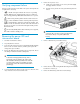
6. Remove the top access cover.
a. Lift the access panel latch (1). The access panel will slightly
disengage from the enclosure.
b. Slide the access panel to the rear (2) and lift away from the
chassis.
NOTE:
A Torx tool with T-10 and T-15 ends is provided inside
the enclosure chassis, on top of the I/O module
housing.
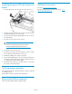
7. Remove cable from the power UID board (1).
8. Remove the T-15 screw securing the LED bezel ring and interconnect
board to the enclosure (2).
9. Remove the LED bezel (3) and interconnect board (4).
Page 2