
HP P6300/P6500 EVA Fibre Channel Controller Enclosure Replacement Instructions (5697-2515, March 2013)
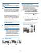
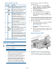
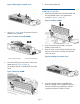
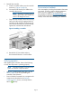

Table 1 Controller status LEDs
IndicationLEDItem
Blue LED identifies a specific controller
module within the enclosure.
1
Green LED indicates controller health.
LED flashes green during boot and
becomes solid green after boot.
2
Flashing amber indicates a controller
termination, or the system is
3
inoperative and attention is required.
Solid amber indicates that the
controller cannot reboot and that the
controller should be replaced. If both
the solid amber and solid blue LEDs
are lit, the controller has completed a
warm removal procedures, and can
be safely swapped.
Indicator is not used on FC controller.
The indicator is used on the FC-iSCSI
MEZZ4
or iSCSI/FCoE controller to indicate
iSCSI module status.
Green LED indicates write-back cache
status. Slow flashing green LED
5
indicates standby power. Solid green
LED indicates cache is good with
normal AC power applied.
Amber LED indicates DIMM status. The
LED is off when DIMM status is good.
6
Slow flashing amber indicates DIMMs
are being powered by battery (during
AC power loss). Solid amber indicates
a DIMM failure.
Removing a controller
CAUTION: Verify the location of the controller
being serviced. Removing the wrong controller
can result in data loss.
NOTE:
• Replacement controllers do not have DIMM
modules, therefore the DIMMs from the
controller being removed must be
transferred to the replacement controller.
• HP recommends that you replace the
controller while the controller enclosure is
powered on to ensure the controller
software on the redundant controller is
copied to the controller being installed.
1. Halt I/O to the controller with HP P6000
Command View:
a. In the navigation pane, select Storage
System→Hardware→Controller Enclosure.
b. Select the controller (Controller 1 or
Controller 2) to halt.
c. Click the Shut down tab.
d. In the Halt Controller section of the Shut
Down Controller window, click Halt. This
halts controller processing while the power
remains on.
2. Disconnect the SAS, Fibre Channel, Ethernet, and
console cables from the halted controller. Ensure
they are marked to facilitate reconnecting later.
3. Remove the controller.
a. Loosen the thumbscrew on the mounting latch
and rotate the latch to the right (1,
Figure 3 (page 3)).
The controller will slightly eject from the
enclosure.
b. Position one hand under the controller, and
with the other hand, pull the controller out of
the enclosure (2).
Figure 3 Removing a controller
4. Push the blue button on top of the controller
module (1, Figure 4 (page 4)) and slide off the
cover (2). Observe proper anti-static guidelines.
Page 3