
HP XP7 Site Preparation Guide (H6F56-96012)
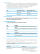
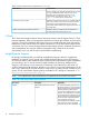
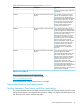
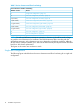
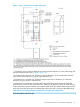
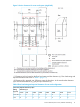
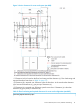
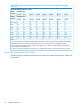

Table 6 XP7 disk array remote support products (continued)
ApplicationDescriptionHP Product
ensure the optimal support model and
highest TCE.
For customers that commit to utilize
Internet and Insight Remote Support
HP XP/XP7 no Remote Device Access
Support
AE242A
connectivity for XP7 Remote Device
Monitoring but will not allow for Remote
Device Access to the XP7 array from
HP for proactive and critical support
processes.With no Remote Device
Access, Critical Support contract
prerequisites cannot be met.
For a customer whose strict security
protocols specifically prohibit inbound/
HP XP/XP7 Mission Critical No LAN
Support
AE244A
outbound traffic to/from the data center
and thus will not allow Remote Support
connection by either modem or
LAN/internet connectivity; but does
have Mission Critical Services with
Customer Engineer onsite included in
the terms of the support contract.
Factory Authorization will be required
to order this product. Proof of valid
Customer Engineer onsite Mission
Critical support contract must be
provided for Factory Authorization
approval.
For a customer whose strict security
protocols specifically prohibit
HP XP/XP7 No Mission Critical LAN
Support
AE245A
inbound/outbound traffic to/from the
data center and thus will not allow
Remote Support connection by either
modem or LAN and does not have a
Mission Critical Services on-site
contract. The added cost of this
configuration only covers the additional
warranty support cost to HP during
warranty period. Other additional costs
can also be incurred for support
contracts for customers who do not have
remote support configured.
Details are available at:
http://www.hp.com/go/insightremotesupport
To download the software, go to Software Depot:
http://www.software.hp.com
Select Insight Remote Support from the menu on the right.
System specifications and requirements
Service clearance, floor cutout, and floor load rating
This section describes the service clearance requirements for XP7 Storage, based on the floor load
rating and the clearance and required floor cutouts for cabling. The figures and tables that provide
this information are listed in the following table.
System specifications and requirements 13