
HP XP7 Site Preparation Guide (H6F56-96012)
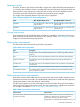
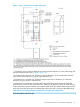
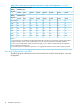
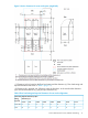
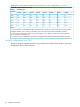
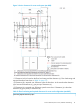
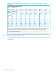

Table 7 Service clearance and floor load ratings
Service Clearance and Floor Load Rating
SectionNumber of racks
“Single rack configuration” (page 14)1
“Two rack configuration (one DKC)” (page 16)2
“Two rack configuration (two DKC)” (page 18)2 (two DKC)
“Three rack configuration (left module)” (page 20)3 (left module)
“Three rack configuration (right module)” (page 22)3 (right module)
“Four rack configuration (left module)” (page 24)4 (left module)
“Four rack configuration (right module)” (page 26)4 (right module)
“Five rack configuration” (page 29)5
“Six rack configuration” (page 30)6
NOTE: For safe and efficient maintenance operations, clearance (c) should be made as large
as possible. Actual clearances for installation should be determined after consulting with the
site/facilities manager, as the clearances can vary, depending on building conditions. Although
all disk chassis come pre-installed, up to 1420 mm of clearance may be required at both front and
back for a disk chassis replacement.
The figures in this section are not drawn to scale.
Single rack configuration
The following figure and table show the service clearances and floor load rating for a single rack
configuration.
14 Installation requirements