
HP XP7 Site Preparation Guide (H6F56-96012)
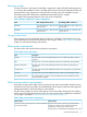
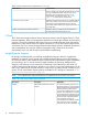
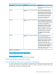
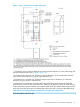
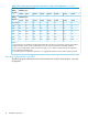
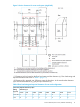
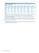
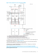
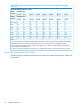

Table 8 Floor load rating and required clearances for single rack configuration (continued)
Required Clearance (a+b) m
Clearance (c) m
Floor Load
Rating
(kg/m2)
C=1.4C=1.0C=0.8C=0.6C=0.4C=0.2C=0C=-0.3
Clearance (c) mRating
(kg/m2)
C=1.4C=1.0C=0.8C=0.6C=0.4C=0.2C=0C=-0.3
00000000Over 700
00000000.1600
00000.10.10.20.3500
00.10.10.10.20.30.30.4450
0.10.20.20.30.30.40.50.6400
0.30.40.40.50.60.60.70.9350
0.50.60.70.80.91.01.11.4300
Notes:
1. Actual clearances for installation should be determined after consulting with construction specialist responsible for
installation building, as they could vary depending on the size/layout of the system and building conditions.
2. When various configurations of disk arrays are arranged in a row, clearance values based on the largest disk
array configuration should be used.
3. From the viewpoint of maintenance operations, it is suggested that Clearance (c) be made as large as possible.
Two rack configuration (one DKC)
The following figure and table shows the service clearances and floor load rating for a two-rack
configuration.
16 Installation requirements