
HP XP7 Business Continuity Manager Reference Guide (TK954-96004)


1 ISPF panels
This chapter explains how to move between ISPF panels and perform operations on them, and the
nature and function of displayed items.
Unless otherwise specified, the term storage system in this guide refers to the following disk arrays:
• HP XP7 Storage
• HP XP P9500 Disk Array
• HP XP24000 Disk Array
• HP XP20000 Disk Array
The examples in this guide show a typical display from the appropriate z/OS interface, for example,
ISPF, console/SYSLOG, command line, and so on. Depending on the specific 3270 terminal
emulation software used, you might see minor differences from the examples as far as formatting
is concerned. However, the content should be displayed.
Business Continuity Manager can control the following replication products:
• BC or BC Z — Business Copy Z/Hitachi ShadowImage for Mainframe (SI)
• CA or Cnt Ac-S Z — Continuous Access Synchronous Z/Hitachi TrueCopy for Mainframe (TC)
• CAJ or Cnt Ac-J Z — Continuous Access Journal Z/Hitachi Universal Replicator for Mainframe
(UR)
• TCA or CAA — Hitachi TrueCopy Asynchronous for Mainframe (TCA)
NOTE: Hitachi TrueCopy Asynchronous (TCA) is supported on the HP XP Disk Array. TCA is not
supported on the XP7 Storage, XP9500 Storage, and XP20000 or XP24000 Disk Arrays. Business
Continuity Manager can be used with both XP P9500 and XP disk arrays. The XP disk array copy
products can be configured and controlled using the XP7 version of BCM. With the exception of
TrueCopy Asynchronous, the HP product names are used in this manual. For compatibility with
existing implementations on XP disk arrays, the Hitachi abbreviations shown in parenthesis are
accepted by the user interface. The graphics in this manual show the HP abbreviations, but your
system may show the Hitachi abbreviations.
Overview of ISPF panels
The Business Continuity Manager panel interface consists of ISPF panels. You can use ISPF panels
to operate Business Continuity Manager and manipulate copy groups. This section describes the
Business Continuity Manager panel system and panel transitions, and gives an overview of ISPF
panels. Note that the following explanations assume the default values for the PF key numbers.
ISPF panel system
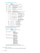
The structure of the operation panels starting from the Main Menus is shown in Figure 1 (page 10)
and Figure 2 (page 10). As the panel system illustration suggests, there are multiple levels of panels.
Tertiary panels are accessed through secondary panels.
Overview of ISPF panels 9