
HP Pavilion 15 Notebook PC HP Pavilion TouchSmart 15 Notebook PC - Maintenance and Service Guide

d. Memory module (see Memory module on page 44).
e. Keyboard (see
Keyboard on page 54).
f. Top cover (see
Top cover on page 59).
g. Hard drive (see
Hard drive on page 63).
h. System board (see
System board on page 73).
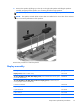
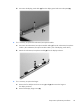
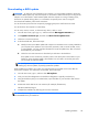
Remove the display assembly:
1. Remove the three Phillips M2.5×6.5 screws (1) and (2) that secure the display assembly to
the base enclosure.
2. Remove the display assembly (3).
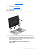
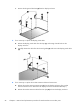
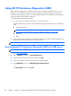
3. If it is necessary to replace the display bezel or any of the display assembly subcomponents:
a. Remove the two display bezel screw covers (1) and the two Phillips M2.5×5.0 screws (2)
that secure the display bezel to the display assembly. The display bezel screw covers are
included in the display bezel spare part kit, spare part number 676644-001, and in all
display assembly subcomponent spare part kits.
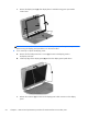
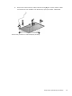
b. Flex the inside edges of the bottom edge (3), the left and right sides (4),
and the top edge (5) of the display bezel until the bezel disengages from
the display enclosure.
Component replacement procedures
93