
HP Pavilion 15 Notebook PC HP Pavilion TouchSmart 15 Notebook PC - Maintenance and Service Guide
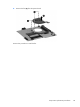
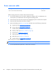
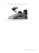

Heat sink assembly
Description Spare part number
Heat sink for use only on computer models equipped with a graphics subsystem with AMD UMA
memory 19 W
734448-001
Heat sink for use only on computer models equipped with a graphics subsystem with AMD UMA
memory 25 W
734449-001
Heat sink for use only on computer models equipped with a graphics subsystem with AMD discrete
memory 19 W
734450-001
Heat sink for use only on computer models equipped with a graphics subsystem with AMD discrete
memory 25 W
734451-001
For use only on computer models equipped with Intel HM76 chipset and UMA graphics 742330-001
For use only on computer models equipped with Intel HM76 chipset and switchable discrete
graphics
742331-001
For use only on computer models equipped with Intel processors and UMA graphics 742581-001
For use only on computer models equipped with Intel processors and switchable discrete graphics 742582-001
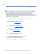
NOTE: To properly ventilate the computer, allow at least 7.6 cm (3 in) of clearance on the left side of
the computer. The computer uses an electric fan for ventilation. The fan is controlled by a temperature
sensor and is designed to turn on automatically when high temperature conditions exist. These
conditions are affected by high external temperatures, system power consumption, power
management/battery conservation configurations, battery fast charging, and software requirements.
Exhaust air is displaced through the ventilation grill located on the left side of the computer.
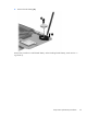
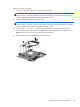
Before removing the fan/heat sink assembly, follow these steps:
1. Turn off the computer. If you are unsure whether the computer is off or in Hibernation, turn
the computer on, and then shut it down through the operating system.
2. Disconnect the power from the computer by unplugging the power cord from the computer.
3. Disconnect all external devices from the computer.
4. Remove the battery (see
Battery on page 42), and then remove the following components:
a. Optical drive (see
Optical drive on page 48).
b. Service door (see
Service door on page 44).
c. WLAN module (see
WLAN module on page 46).
d. Memory module (see
Memory module on page 44).
e. Keyboard (see
Keyboard on page 54).
f. Top cover (see
Top cover on page 59).
g. Hard drive (see
Hard drive on page 63).
h. System board (see
System board on page 73).
84 Chapter 6 Removal and replacement procedures for Authorized Service Provider parts