Upgrading and Servicing Guide
The only warranties for Hewlett-Packard products and services are set forth in the express statements accompanying such products and services. Nothing herein should be construed as constituting an additional warranty. HP shall not be liable for technical or editorial errors or omissions contained herein. HP assumes no responsibility for the use or reliability of its software on equipment that is not furnished by HP. This document contains proprietary information that is protected by copyright.
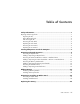
Table of Contents Safety Information...................................................................................1 Opening and Closing the PC ...................................................................................1 Preparing the PC ...............................................................................................2 Before Opening the PC ......................................................................................2 After Closing the PC..................................
iv Table of Contents
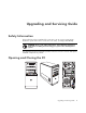
Upgrading and Servicing Guide Safety Information This product has not been evaluated for connection to an “IT” power system (an AC distribution system with no direct connection to the earth, according to IEC 60950). WARNING: Please read “Safety Information” in the Warranty and Support Guide before installing and connecting your system to the electrical power system. The Upgrading and Servicing Guide provides instructions on how to remove and replace hardware components of your PC.
Preparing the PC Before you upgrade any component in your PC, you need to prepare the PC so that you can safely handle it and the components. Read the following items before attempting to upgrade or service the PC: 1 These procedures assume familiarity with the general terminology associated with personal computers and with the safety practices and regulatory compliance required for using and modifying electronic equipment.
After Closing the PC To avoid injury and equipment damage, always follow this procedure in this order after closing the PC: 1 Reconnect the power cord. WARNING: To reduce the risk of electrical shock, fire, or damage to the equipment, do not plug telecommunications or telephone connectors into the network interface card (NIC) (labeled as an Ethernet connector). 2 Reconnect the modem/telephone cable and all other cables (such as the keyboard, mouse, and monitor). 3 Reconnect external devices.
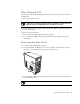
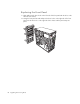
Replacing the Side Panel 1 Align the tabs at the bottom of the side panel to the ridge on the bottom of the chassis. Place the side panel in the proper position on the chassis and slide it toward the front of the chassis. A NOTE: There is a 3mm gap between the top of the side panel and the top of the chassis when the side panel is attached properly. 2 Ensure that the hole for the thumbscrew aligns with the hole in the chassis, and then replace the thumbscrew (A). 3 See “After Closing the PC” on page 3.
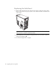
Removing the Front Panel This procedure is necessary only when removing or replacing an optical drive, memory card reader, an HP Pocket Media Drive, diskette drive, or the hard disk drive. 1 Pull the three tabs (B) away from the outside edge of the chassis. B 2 Swing the front panel away from the chassis toward the left to remove it.
Replacing the Front Panel 1 Align and insert the three hooks on the left side of the front panel with the holes on the left side of the chassis. 2 Swing the front panel around and press the three hooks on the right side of the front panel into the three holes on the right side of the chassis until the panel snaps into place.
Locating Components Inside the Computer A B C D E F A Memory card reader (select models) B Upper 5.25-inch optical drive bay, may be a CD-ROM, CD-RW, DVD-ROM, DVD+RW/+R, or combination drive C Lower 5.
Removing and Replacing Drives Your PC has several drives that you can replace or upgrade. See the preceding topic, “Locating Components Inside the Computer” on page 7 for drive type and location. The hard disk drive is either a Serial ATA (advanced technology attachment) drive, which uses a narrow data cable, or a Parallel ATA drive, which uses a wide data cable. Select models have a second hard disk drive.
3 Disconnect the power, data, and the sound cable, if available, from the back of the optical drive you want to remove. For most drive cables, use a gentle rocking motion to free the plug. For Serial ATA hard disk drive cables, press the latch (select models only) in the center of each plug, and pull the plug from the drive connector. 4 Pull the drive out through the front of the chassis. Adding or Replacing an Optical Drive 1 If necessary, remove the existing drive.
4 Make sure the jumper on the new optical drive or new Parallel ATA hard disk drive is in the CS (Cable Select) position. Your drive may vary from the illustration. The Serial ATA hard disk drive does not use Cable Select. CS SL MA Cable Select jumper 5 Release the drive bay by pulling the latch out away from the chassis and then sliding the drive part way into the front of the chassis. (The latch drive brackets secure the drives in their respective positions in the chassis.
6 Connect the power and data cables from the back of the optical drive you want to add. Reconnect the sound cable, if present. WARNING: For a second Parallel ATA drive, make sure to connect the data cable labeled Master to the primary hard disk drive, and the data cable labeled Slave to the secondary hard disk drive. If the data cable is not connected correctly, the PC is unable to locate the hard disk drive and data may be lost.
3 Disconnect the power and data cables from the back of the drive by squeezing the two latches and pulling the cable. MA ST ER SLA VE To C PU 4 Pull the drive out through the front of the chassis.
Adding or Replacing the HP Pocket Media or Diskette or Hard Disk Drive 1 Complete the procedures to remove the HP Pocket Media, diskette (floppy), or hard disk drive, if necessary. See “Removing the HP Pocket Media or Diskette or Hard Disk Drive” on page 11. 2 Slide the HP Pocket Media, diskette (floppy), or hard disk drive into the front of the chassis until it locks into place. 3 Align the two screw holes on the chassis with the two screw holes on the side of the drive, and then attach the two screws.
4 Connect the power and data cables to the back of the HP Pocket Media, diskette (floppy), or hard disk drive. A B MA ST ER SLA VE C To C PU A — Connect to a primary hard disk drive. B — Connect to a secondary hard disk drive (select models only). C — Connect to the PC motherboard. 5 Complete the procedures to replace the front panel, replace the side panel, and close the PC. See “Opening and Closing the PC” on page 1.
Removing the Memory Card Reader 1 Complete the procedures to prepare the PC to remove the side panel and to remove the front panel. See “Opening and Closing the PC” on page 1. 2 Release the drive by removing the screw on the top of the memory card reader, sliding the reader to the left to loosen it, and then pulling the memory card reader part way out of the front of the chassis. 3 Disconnect the cable from the back of the memory card reader. 4 Pull the memory card reader out of the front of the chassis.
Adding or Replacing the Memory Card Reader 1 Complete the procedures to remove the memory card reader, if necessary. See “Removing the Memory Card Reader” on page 15. 2 Slide the memory card reader part way into the front of the chassis. 3 Attach the cable to the back of the memory card reader.
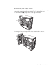
Removing the Hard Disk Drive 1 Complete the procedures to prepare the PC to remove the side panel and to remove the front panel. See “Opening and Closing the PC” on page 1. 2 Lay the computer gently on its side. 3 Remove the two screws that secure the hard disk drive cage to the chassis. 4 Push down the latch on the side of the hard disk drive cage, and then slide the hard disk drive cage away from the bottom of the chassis as shown below.
5 Lift the hard disk drive cage out of the chassis, and then remove the hard disk drive cables (1, 2). For most drive cables, use a gentle rocking motion to free the plug. For Serial ATA hard disk drive cables, press the latch (5) (select models only) in the center of each plug (6), and pull the plug from the drive connector.
6 Remove the four screws that secure the hard disk drive to the hard disk drive cage, and then slide the hard disk drive out of the hard disk drive cage. Adding or Replacing a Hard Disk Drive 1 If necessary, remove the existing drive. See “Removing the Hard Disk Drive” on page 17. 2 Slide the new drive into the hard disk drive cage, aligning the drive with the four screw holes on the cage. Install the four screws that secure the hard disk drive to the hard disk drive cage.
3 Place the hard disk drive cage into the chassis. The two screw holes on the hard disk drive cage (A) should be aligned with the screw holes on the chassis (B). A B 4 Align the four guides on the bottom of the hard disk drive cage with the holes on the back of the chassis, and then slide it down toward the bottom of the chassis until it locks into place.
5 Attach the hard disk drive cables. A B MA ST ER SLA VE C To C PU A — Connect to a primary hard disk drive. B — Connect to a secondary hard disk drive (select models only). C — Connect to the PC motherboard. 6 Attach the two screws that secure the hard disk drive cage to the chassis. 7 Complete the procedures to replace the front panel, replace the side panel, and close the PC. See “Opening and Closing the PC” on page 1.
Adding Memory Your PC comes with random access memory (RAM), which temporarily stores data and instructions on your PC. The PC ships with one or more memory modules, but you can replace the existing memory module(s) with higher-capacity ones. The motherboard contains sockets for DDR DIMMs (double data rate dual in-line memory modules). The exact number of sockets and type of DDR memory module depends on which model PC you have.
Removing a Memory Module 1 Complete the procedures to prepare the PC and to remove the side panel. See “Opening and Closing the PC” on page 1. 2 Gently lay the PC on its side. 3 Locate the memory sockets on the motherboard. CAUTION: When handling a memory module, be careful not to touch any of the contacts. Doing so may damage the module. 4 Move any cabling out of the way, if necessary. 5 Push down the two retaining clips on the ends of the memory socket until the memory module pops out of the socket.
Installing a Memory Module Upgrade the memory in your PC with memory of the same type and speed as the memory originally installed in your PC. CAUTION: When handling a memory module, be careful not to touch any of the contacts. Doing so may damage the module. 1 Open both latches of the memory module socket: If you are replacing a memory module, put the new memory module in the same memory slot from which the old memory was removed.
Removing or Installing an Add-in Card An add-in card is a circuit board, such as a PCI or an AGP card, that fits into a PC add-in card slot. Your PC contains several add-in card slots that can be used to add components to your PC. The PC component configurations vary by model. WARNING: Do not overload the system by installing add-in cards that draw excessive current. The system is designed to provide two amps (average) of +5 Vv power for each board/card in the computer.
Removing an Add-in Card 1 Complete the procedures to prepare the PC and to remove the side panel. See “Opening and Closing the PC” on page 1. 2 Gently lay the PC on its side. 3 On the back of the PC, remove the screw from the bracket cover for the add-in card slots, and then remove the bracket cover. 4 Inside the PC, locate the add-in card slots on the motherboard. WARNING: Be careful of the sharp edges on the add-in card slot cover. 5 Remove the slot cover.
Installing an Add-in Card 1 Align the edge of the add-in card with the slot on the chassis and gently but firmly press the card straight down into the add-in card slot. The whole connector should be seated properly in the card slot. 2 On the back of the PC, replace the bracket cover for the add-in card slots, and then install the screw. 3 Set the chassis upright. 4 Complete the procedures to replace the side panel, and close the PC. See “Opening and Closing the PC” on page 1.
Replacing the Battery A lithium battery on the motherboard provides backup power for the PC’s timekeeping ability. The battery has an estimated life expectancy of seven years. When the battery starts to weaken, the date and time may be incorrect. If the battery fails, replace it with a CR2032 lithium battery (3 volt, 220mAH rating) or an equivalent battery. WARNING: There is danger of explosion if the battery is incorrectly replaced. Replace only with the same, or equivalent, type of battery.