AH303A PCIe SC44Ge SAS Host Bus Adapter for Integrity Servers Support Guide HP-UX 11i v2, 11i v3 HP Part Number: 5900-0111 Published: August 2009 Edition: 4
© Copyright 2009 Hewlett-Packard Development Company L.P. Legal Notices The information contained herein is subject to change without notice. The only warranties for HP products and services are set forth in the express warranty statements accompanying such products and services. Nothing herein should be construed as constituting an additional warranty. HP shall not be liable for technical or editorial errors or omissions contained herein.
Table of Contents About This Document ........................................................................................................7 Intended Audience.................................................................................................................................7 New and Changed Documentation in This Edition...............................................................................7 Publishing History............................................................................
DELETE......................................................................................................................................35 Syntax....................................................................................................................................35 Parameters ............................................................................................................................35 Operation.................................................................................
Canadian Notice...................................................................................................................................63 European Union Regulatory Notice.....................................................................................................63 BSMI Notice..........................................................................................................................................64 Japanese Class A Notice....................................................
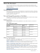
About This Document This document describes how to install, configure, and troubleshoot the AH303A Host Bus Adapter on HP-UX 11i v2 and 11i v3 platforms. The latest version of this document is available on the HP website at: http://docs.hp.com/en/netcom.html Intended Audience This document is for system and network administrators responsible for installing, configuring, and managing fault tolerant data storage. Administrators must know HP-UX operating system concepts, commands, and configuration.
Appendix C “Regulatory Compliance Notices” provides regulatory compliance statements. Related Documents For additional information about the AH303A Host Bus Adapter, see: http://docs.hp.com/en/netcom.html Other documents in this collection include: • • • SerialSCSI-00 (sasd) Mass Storage Driver Release Notes HP CommonIO Release Notes SAS Host Bus Adapters Support Matrix HP Encourages Your Comments HP encourages your comments concerning this document.
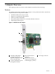
1 Adapter Overview This chapter provides an overview of the AH303A controller and its technology. Features The AH303A PCIe SC44Ge SAS Host Bus Adapter is a low-profile, 64-bit PCIe controller for external SAS devices. Key features include: • • • • • SAS data transfer rates of up to 3 Gb/s Support for SAS Ultrium tape products PCIe x8 (2.
2 Installation This chapter provides procedures to install the AH303A Host Bus Adapter.
http://docs.hp.com/en/netcom.html 2. Confirm that you have the correct operating system drivers available. The AH303A adapter is supported by the CommonIO and SerialSCSI-00 bundles, available on Application Release CDs or the HP Software Depot website.
12. In the Documents column next to the Download Software column, click Download/Installation Instructions to view instructions for using the swinstall tool to install the drivers, utilities, and manpages. Installing Software The drivers, utilities, and manpages for SAS controllers are contained in the CommonIO and SerialSCSI-00 bundles located in the downloaded depots. See “Downloading Software” (page 12).
6. 7. Depending on the server model, secure the adapter by replacing the retaining screw or by closing the slot latch. Replace and secure the server access panel. Completing the Adapter Installation To complete the adapter installation, follow these steps: 1. 2. 3. 4. 5. 6. Verify the cable connections to the external disks. Reconnect peripheral devices to the server. Plug the AC power cord into the server, and then into a grounded AC outlet. Power on peripheral devices attached to the server.
3. Install the adapter in your HP-UX system according to the procedure described in the latest edition of the Interface Card OL* Support Guide for 11i v2 or v3: • For instructions on using OL* on HP-UX 11i v2, see the Interface Card OL* Support Guide: http://docs.hp.com/en/oshpux11iv2.html • For instructions on using OL* on HP-UX 11i v3, see the Interface Card OL* Support Guide: http://docs.hp.com/en/oshpux11iv3.
You can order additional cables from an authorized HP reseller or an authorized HP service provider. If the cable you need is not listed here, or if you need additional ordering information, see the HP website at: http://www.hp.com Updating System Firmware The system firmware on HP Integrity® systems is based on the Extensible Firmware Interface (EFI) specifications. You can use an EFI utility offline to verify the system firmware version installed on HP Integrity systems.
The sasflash.efi utility and firmware images are included on the IPF Offline Diagnostics and Utilities CD, version 0803 and later. To update the adapter firmware offline, follow the procedures provided with the sasflash utility. CAUTION: If you have updated the adapter firmware using sasflash, booting a disk with an older version of SerialSCSI-00 (including Ignite-UX) might download an older version of the firmware and EFI driver to all HBAs controlled by SerialSCSI-00 in the system.
3 Configuring the Adapter Offline This chapter describes using EFI utilities to configure the AH303A controller offline. This chapter includes the following topics: “EFI Utilities” “The drvcfg Configuration Utility” (page 19) “The cfggen Utility” (page 34) EFI Utilities You can use EFI utilities to configure the SAS Host Bus Adapter on your HP Integrity server.
Configuration Utility Screens SAS BIOS configuration utility screens contain the following areas, starting at the top of the screen: • • • • Header area: Identifies the utility and version number. Menu area: Gives the title of the current screen, and on screens other than the Adapter List screen also identifies the adapter. Main area: The main area for presenting data. This area has a cursor for item selection, and horizontal and vertical scroll bars if necessary.
Status Indicates whether the adapter is eligible for software control: Enabled, Disabled, or Error. Enabled Indicates the EFI driver is controlling the adapter or will attempt to control the adapter upon reload. Disabled Indicates the EFI driver is not controlling the adapter or will discontinue control of the adapter upon reload. Error Indicates that the EFI driver encountered a problem with the adapter.
Boot Support Enabled Indicates the EFI driver is controlling the adapter, or will attempt to control the adapter upon reload. Disabled Indicates the EFI driver is not controlling the adapter or will discontinue control of the adapter upon reload. Error Indicates that the EFI driver encountered a problem with the adapter. You can view and modify settings for the adapter but the available information and functionality may be limited.
SAS Topology Screen To access the SAS Topology screen, highlight the SAS Topology field on the Adapter Properties screen and press Enter. A screen similar to the following appears: Use the SAS Topology screen to view the adapter's SAS hierarchy, and to access enclosure and device properties. To view the properties of an enclosure and its installed devices, highlight the enclosure name in the Device Identifier field and press Enter.
This expanded enclosure screen lists devices in the enclosure. The columns display device properties, as follows: SAS1068E (address) Indicates the location (bay) of each device in the enclosure. Device Identifier Indicates the ASCII device identifier string from the device's inquiry data. Device Info Indicates the device type (SAS or SATA). Only SAS devices are supported. To display the Device Properties screen for a device and turn on its locate LED, highlight the device name and press D.
The information fields on the Device Properties screen are as follows: Device Identifier Indicates the ASCII device identifier string from the device's inquiry data. Scan Order Indicates the scan order of the disk. Slot Number Indicates the slot location of the disk in the enclosure. Device Information Indicates the device type (SAS or SATA). Only SAS disks are supported. SAS Address Indicates the SAS address of the device. Serial Number Indicates the serial number for this device.
Use the Device Format screen to perform a low-level format of the device. The default format is 512-bytes per sector. The information fields on the Device Format screen are as follows: Device Identifier Indicates the ASCII device identifier from the device's inquiry data. SAS Address Indicates the SAS Address of the device. Serial Number Indicates the serial number of the device. Elapsed Time Displays the time elapsed since the start of the operation.
Use the Verify screen to verify the sectors on the device and reassign defective Logical Block Addresses (LBAs). The information fields on the Device Verify screen are as follows: Device Identifier Indicates the ASCII device identifier from the device's inquiry data. SAS Address Indicates the SAS address of the device. Serial Number Indicates the serial number of the device. Elapsed Time Displays the time elapsed since the start of the operation.
Information fields on the Advanced Adapter Properties screen are as follows: IRQ Indicates the Interrupt Request Line used by the adapter. This is assigned by the system BIOS. NVM Indicates whether the adapter has nonvolatile memory (NVM), which is used to store configuration settings. Chip Revision ID Indicates the revision ID of this adapter.
Running Disparity Errors Indicates the number of DWORDs with running disparity errors that have been received (outside of PHY reset sequences) since the last PHY Link Error reset. PHY REset Errors Indicates the number of times the PHY Reset sequence has failed since the last PHY Link Error Reset. To access the following additional screens, use the arrow keys to highlight the option and press Enter: • • • Advanced Device Properties. See “Advanced Device Properties Screen.” Spinup Properties.
NCQ Native Command Queuing for SATA devices: Enabled or Disabled. • Disabled: Default setting. • Enabled: Not supported at the time of publication.
To toggle between LUN 0 and All, press + or -. LUN 0 scans only LUN 0. All scans all LUNs. LUNs to Scan for Sequential Devices Controls LUN scans for “SCSI Device Type 01h - Sequential Access” devices.
To return to the Advanced Adapter Properties screen, press Esc. PHY Properties Screen To access the PHY Properties screen, highlight the PHY Properties field on the Advanced adapter Properties Screen and press Enter. A screen similar to the following appears: Use the PHY Properties screen to view and modify PHY settings. Information fields on the PHY Properties screen are as follows: 32 PHY Indicates the active PHY number.
Device Identifier Indicates the ASCII device identifier string extracted from the device's inquiry data. Scan Order Indicates the scan order for this device. This is equivalent to the SCSI ID value in parallel SCSI configurations. Device Information Indicates whether a device is SAS. SAS Address Indicates the SAS address of the device. Link Error Settings Invalid DWORDs Number of invalid DWORDs received outside of PHY reset sequences since the last PHY link error reset.
To perform the reset, highlight an option and press Enter. Exiting drvcfg Because some changes only take effect when you exit drvcfg, follow these steps to exit the utility: 1. 2. From Adapter Properties press Esc to return to the Adapter List. From the Adapter List, press Esc to exit the utility. The exit screen shows some options that are grey, indicating they are not available. Only available options are selectable.
NOTE: Separate the program name, controller number, command, and parameters fields with the ASCII space character. The format of the parameters is command specific. The program return value is returned to the user when the program exits. If the command is successful a value of 0 is returned, otherwise, a value of 1 is returned. The cfggen Command Set DELETE Use the DELETE command to set the controller configuration to factory defaults.
----------------------------------------------------------------------------------------------------------------------------------------------Physical device information -----------------------------------------------------------------------Initiator at ID #112 Target on ID #10 Device is a Hard disk Enclosure # : 2 Slot # : 2 Target ID : 10 State : Ready (RDY) Size (in MB)/(in sectors) : 70007/143374738 Manufacturer : HP Model Number : DH072ABAA6 Firmware Revision : HPD2 Serial No : 3PD08ZHT000097404JK9 Dri
Target on ID #15 Device is a Hard disk Enclosure # Slot # Target ID State Size (in MB)/(in sectors) Manufacturer Model Number Firmware Revision Serial No Drive Type Target on ID #16 Device is a Hard disk Enclosure # Slot # Target ID State Size (in MB)/(in sectors) Manufacturer Model Number Firmware Revision Serial No Drive Type Target on ID #17 Device is a Hard disk Enclosure # Slot # Target ID State Size (in MB)/(in sectors) Manufacturer Model Number Firmware Revision Serial No Drive Type Target on ID #18
State Size (in MB)/(in sectors) Manufacturer Model Number Firmware Revision Serial No Drive Type Target on ID #21 Device is a Hard disk Enclosure # Slot # Target ID State Size (in MB)/(in sectors) Manufacturer Model Number Firmware Revision Serial No Drive Type Target on ID #22 Device is a Hard disk Enclosure # Slot # Target ID State Size (in MB)/(in sectors) Manufacturer Model Number Firmware Revision Serial No Drive Type Target on ID #23 Device is a Hard disk Enclosure # Slot # Target ID State Size (in MB
Serial No Drive Type Target on ID #26 Device is a Hard disk Enclosure # Slot # Target ID State Size (in MB)/(in sectors) Manufacturer Model Number Firmware Revision Serial No Drive Type Target on ID #27 Device is a Hard disk Enclosure # Slot # Target ID State Size (in MB)/(in sectors) Manufacturer Model Number Firmware Revision Serial No Drive Type Target on ID #28 Device is a Hard disk Enclosure # Slot # Target ID State Size (in MB)/(in sectors) Manufacturer Model Number Firmware Revision Serial No Drive T
Slot # : 25 Target ID : 33 State : Ready (RDY) Size (in MB)/(in sectors) : 70007/143374738 Manufacturer : HP Model Number : DH072ABAA6 Firmware Revision : HPD2 Serial No : 3PD09M7500009742SMWP Drive Type : SAS Target on ID #34 Device is a Enclosure services device Enclosure # : 2 Slot # : 26 Target ID : 34 State : Standby (SBY) Manufacturer : HP Model Number : MSA70 Firmware Revision : 2.
WARNING! Performing a low-level format on a hard disk drive destroys all data stored on that disk. Do not interrupt the operation. Doing so can result in irreparable damage to the hard disk. Operation Unless you include on the command line, warning messages appear. You must answer a series of prompts or the command is aborted. The answers are case sensitive and you must enter them in upper case. This command returns to a shell prompt when the format operation is complete.
fs0:\EFI30305> cfggen 1 create IM MAX 14 15 LSI Logic SAS Raid Configuration Utility v1.00.13.00 Executing Create Command cfggen: ERROR - Controller number "1" - Integrated RAID (IR) functionality is disabled on the controller.
4 Configuring and Troubleshooting the Adapter Online This chapter describes the troubleshooting and maintenance tools available for the AH303A Host Bus Adapter.
For more information about ODE, see the documents in the Offline Diagnostic section at: http://docs.hp.com/en/diag.html Troubleshooting With HP-UX Utilities Online Use the ioscan and sasmgr utilities to perform troubleshooting on the AH303A and its attached devices. The ioscan Utility By default, ioscan scans the system and lists all reportable hardware found. The types of hardware reported include processors, interface cards, and I/O devices.
escsi_ctlr 0 escsi_ctlr 1 0/1/1/0 sasd CLAIMED /dev/sasd0 0/2/0/0/0/0 sasd CLAIMED /dev/sasd1 INTERFACE HP PCI/PCI-X SAS MPT Adapter INTERFACE HP PCI-E SAS MPT Adapter Use the ioscan -fnH command to display information about disk devices on an adapter.
ext_bus target disk 4 3 42 0/2/0/0/0/0.0.2 sasd_vbus 0/2/0/0/0/0.0.2.6 tgt 0/2/0/0/0/0.0.2.6.0 sdisk /dev/dsk/c4t6d0 CLAIMED INTERFACE CLAIMED DEVICE CLAIMED DEVICE /dev/rdsk/c4t6d0 SAS Device Interface HP DH072ABAA6 By default, for each hardware module on the system ioscan displays the hardware path to the hardware module, the class of the hardware module, and a brief description. If the device is connected but not found, it is in a “no hardware” state.
sasmgr [-h] get_info -D device_file -q smp_addr sasmgr [-h] get_info -D device_file -q target={all | sasaddr} sasmgr [-h] get_info -D device_file -q vpd sasmgr [-h] get_stat -D device_file sasmgr [-h] get_stat -D device_file -q phy={all | phy_id} sasmgr [-h] get_stat -D device_file -q phy_in_port={all | phy_id} sasmgr [-h] get_stat -D device_file -q target={all | sasaddr} sasmgr [-h][-f] replace_tgt -D device_file -q old_dev=lun_dsf -q new_tgt_hwpath=new_hw_path sasmgr [-h][-f] reset -D device_file sasmgr [
disable Disables the controller. This is a destructive operation. The controller goes offline, all current I/Os are aborted, and new I/Os fail. You must perform an enable operation to bring the controller back online. If the -f option is not specified, sasmgr displays a warning message before continuing the command. Otherwise, it suppresses the warning message and executes the command. download Updates the firmware on a SAS controller, enclosure, or SAS disk.
get_stat When run without qualifiers, it shows statistics about the controller represented by device_file. You can specify the following qualifiers: • phy – Shows statistics for all PHYs or a specific PHY. • phy_in_port – Shows statistics for a port that the specified PHY belongs to or provides statistics for all ports. • target – Shows statistics for a specific target or all targets.
Info for PHY ID PHY Health Port SAS Address Attached SAS Address Current Link Rate Max Link Rate : : : : : : 1 DOWN 0x0 0x0 1.5 Gbps 1.5 Gbps Info for PHY ID PHY Health Port SAS Address Attached SAS Address Current Link Rate Max Link Rate : : : : : : 2 DOWN 0x0 0x0 1.5 Gbps 1.5 Gbps Info for PHY ID PHY Health Port SAS Address Attached SAS Address Current Link Rate Max Link Rate : : : : : : 3 DOWN 0x0 0x0 1.5 Gbps 1.
/dev/rdsk/c1t5d0 /dev/rdsk/c1t6d0 /dev/rdsk/c1t7d0 /dev/rdsk/c1t8d0 /dev/rdsk/c1t9d0 /dev/rdsk/c2t0d0 /dev/rdsk/c2t1d0 /dev/rdsk/c2t2d0 /dev/rdsk/c2t3d0 /dev/rdsk/c2t4d0 /dev/rdsk/c2t5d0 /dev/rdsk/c4t6d0 0/2/0/0/0/0.0.0.5.0 0/2/0/0/0/0.0.0.6.0 0/2/0/0/0/0.0.0.7.0 0/2/0/0/0/0.0.0.8.0 0/2/0/0/0/0.0.0.9.0 0/2/0/0/0/0.0.1.0.0 0/2/0/0/0/0.0.1.1.0 0/2/0/0/0/0.0.1.2.0 0/2/0/0/0/0.0.1.3.0 0/2/0/0/0/0.0.1.4.0 0/2/0/0/0/0.0.1.5.0 0/2/0/0/0/0.0.2.6.
No. No. No. No. No. No. No. of of of of of of of IOs IOs IOs TMs TMs TMs TMs from from from from from from from SCSI SCSI SCSI SCSI SCSI SCSI SCSI layer layer layer layer layer layer layer failed timedout on active q implicitly aborted succeeded failed timedout on active q OLAR Statistics No. of times HBA went to suspended state Time at which HBA was suspended No. of times HBA resumed No. of times HBA resume failed No.
No. of IO overruns No. of IO underruns No. of IO data length mismatch : 0 : 3644 : 0 TM Statistics NOTE: TM stats are derived from target stats. NOTE: Clearing target stats affects TM stats. No. of TMs posted to HAL No. of TMs aborted on ccb_send_list No. of TMs timed-out on iotm_res_wait_q No. of TMs aborted on iotm_res_wait_q No. of TMs implicitly aborted No. of times TM could not get SM No. of TMs failed because target was dead No. of TMs queued because target was transient No.
Doorbell interrupt timeout count Doorbell response timeout count HAL resource allocation retry count Flash f/w update count No resource to ACK count No resource to process Device event count No resource to process PHY event count Reply frame bounds error count Reply frame offset error count ISR Stale tag count Stale tag count Time IT-NXS Abort was issued : : : : : : : : : : : : 0 0 0 0 0 0 0 0 0 0 0 N/A Context Reply for non-IO count Tag bounds check fail count Heart Beat bad reply status count Internal
# sasmgr get_stat -D /dev/sasd1 -q phy=all Mon Oct 15 16:10:08 2007 Statistics for PHY ID No. of times PHY came UP Time PHY came UP No. of times PHY went Down Time PHY went Down Seconds since PHY statistics was last cleared : : : : : : 0 0 N/A 3 Wed Dec 31 17:00:00 26750 Statistics for PHY ID No. of times PHY came UP Time PHY came UP No. of times PHY went Down Time PHY went Down Seconds since PHY statistics was last cleared : : : : : : 1 0 N/A 3 Wed Dec 31 17:00:00 26750 Statistics for PHY ID No.
No. of Running Parity Errors No. of Loss Dword Syncs No. of PHY Reset Problems encountered : 0 : 0 : 0 Statistics for PHY ID No. of Invalid Dwords No. of Running Parity Errors No. of Loss Dword Syncs No. of PHY Reset Problems encountered : : : : : 1 0 0 0 0 Statistics for PHY ID No. of Invalid Dwords No. of Running Parity Errors No. of Loss Dword Syncs No. of PHY Reset Problems encountered : : : : : 2 0 0 0 0 Statistics for PHY ID No. of Invalid Dwords No. of Running Parity Errors No.
The firmware download process can take a long time to complete (typically, 10-15 minutes). During this time, all I/Os to the controller specified by sasdX are halted. If the controller has a boot logical drive configured, use DFDUTIL from the EFI shell to update the enclosure firmware offline. For more information, see the sasmgr(1M) manpages.
Recommendations Updating Physical Disk Firmware Consider the following when you update the firmware of physical disks attached to the AH303A Host Bus Adapter with sasmgr(1M): • • If you are updating the firmware on more than one disk, do not issue multiple disk firmware download commands on the same command line. Use individual commands for each disk that is to be updated.
A Electrostatic Discharge This appendix discusses ways to prevent damage to your system due to Electrostatic Discharge (ESD). This appendix addresses the following topics: “Handling Parts” (page 59) “Grounding” (page 59) Handling Parts To prevent damage to your system, you must take precautions when setting up the system or handling parts. A discharge of static electricity from a finger or other conductor can damage system boards or other static-sensitive devices.
B Specifications AH303A Host Bus Adapter Specifications Table B-1 AH303A Host Bus Adapter Physical Specifications Dimensions (excluding bracket) 16.8 x 6.4 x 1.6 cm (6.6 x 2.5 x 0.
C Regulatory Compliance Notices This appendix contains regulatory compliance notices. Federal Communications Commission Notice This equipment has been tested and found to comply with the limits for a Class A digital device, pursuant to Part 15 of the FCC Rules. These limits are designed to provide reasonable protection against harmful interference when the equipment is operated in a commercial environment.
BSMI Notice Japanese Class A Notice Korean Class A Notice 64 Regulatory Compliance Notices
Declaration of Conformity Declaration of Conformity 65