
AD193A/AD194A PCI-X 4 Gigabit Fibre Channel and Gigabit Ethernet Combination Card Overview


Hardware and Software Installation Procedure
11
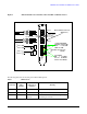
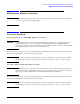
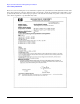
Figure 1 AD194A PCI-X 2-Port 4 Gb FC/ 2-Port 1000B-T Combination Card
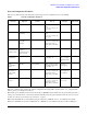
The following table shows the meaning of the different LED patterns:
Table 3 LED Patterns
Card State
LED 1
Ye l l ow
(4Gbit/s)
LED 2
Amber/Green
(2/1Gbit/s)
Meaning
Power Off Off Off Card doesn’t have power
Power On On Amber On Card powered on and not initialized
Power On 1 Flash/s Amber
1 Flash/s
After firmware initialization, Awaiting Link Up.
All flashing at same time.
(Duplex LC)
Fibre Channel Connectors
PCI-X
133 MHz
1000Base-T Connectors
(RJ-45)
Speed LEDS (Port 2)
LED1
LED2
Speed LEDS (Port 1)
LED2 (1 or 2 Gbit/s)
LED1 (4 Gbit/s)
Speed LEDs
Off = 10 Mbit/s
Green = 100 Mbit/s
Yellow = 1000 Mbit/s
Activity/Link LEDs
Flashing = Data traffic
Solid = Active link
OFF = No link
}
Port 1
Port 2
LAN A
LAN B