
AD221A, AD222A, and AD393A PCIe 4 Gigabit Fibre Channel and Gigabit Ethernet Combination Card Overview


Product Overview: AD221A, AD222A, and AD393A
Supporting Systems
7
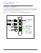
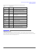
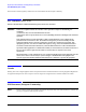
The following table shows the meaning of the different Fibre Channel LED patterns:
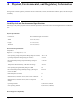
Supporting Systems
For the list of systems that support the cards and the ones that don’t, refer to the Ethernet Support Matrix and the Fibre
Channel Support Matrix on http://docs.hp.com. Those matrixes also tells which OEs support each card, the driver associated
with each card, and the number of cards supported per server.
Table 1 LED Patterns
Yellow Green LED Meaning
1 blink On Normal Operation (1 Gb link rate, link up)
2 blinks On Normal Operation (2 Gb link rate, link up)
3 blinks On Normal Operation (4 Gb link rate, link up)
Off Slow blink Normal (link down or not started)
Off Off Card doesn’t have power. Slot not powered, or card
failed initialization.
On Off POST Failure (dead board)
Slow blink Off Wake-Up Failure Monitor
Fast blink Off POST Failure
Flashing Off POST Process in Progress
Off On Failure While Functioning
On On Failure While Functioning
Slow blink Slow blink Offline for Download
Fast blink Slow blink Restricted Offline Mode (waiting for restart)
Flashing Slow blink Restricted Offline Mode (test active)