HP Performance Optimized Datacenter 20c User Guide - China Abstract This guide is intended for the person who operates and maintains the HP Performance Optimized Datacenter 20c (HP POD 20c).
© Copyright 2012 Hewlett-Packard Development Company, L.P. The information contained herein is subject to change without notice. The only warranties for HP products and services are set forth in the express warranty statements accompanying such products and services. Nothing herein should be construed as constituting an additional warranty. HP shall not be liable for technical or editorial errors or omissions contained herein. Confidential computer software.
Contents Overview ..................................................................................................................................... 6 Before you begin....................................................................................................................................... 6 Operator safety......................................................................................................................................... 6 Component safety ................................
HP POD 20c lighting ............................................................................................................................... 29 Environmental control system ........................................................................................................ 31 Environmental control system overview ....................................................................................................... 31 Using the ECS ................................................................
Rack specifications .................................................................................................................................. 76 Thermal and air flow performance ............................................................................................................. 76 Environmental specifications ..................................................................................................................... 76 Maintenance .................................................
Overview Before you begin For more information on site requirements, specifications, power requirements, management requirements, and supported facility connections, see the HP Performance Optimized Datacenter 20c Site Preparation and Requirements Guide. The actual location of various components or included subsystems in your HP POD 20c might vary from what is described in this document.
CAUTION: If any racks contain empty RU space, use the HP POD 20c filler panels to maintain the efficiency of the HP POD 20c thermal system. Filler panels are available from HP in 10-pack quantities (part number AQ682A) and 100-pack quantities (part number AS993A). Fire suppression The fire suppression system, supplied as an optional component of the HP POD 20c, is a "Manufacturer Designed" system specifically for this HP product, in compliance with national standards.
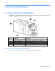
Component identification Structural component identification The HP POD 20c documentation frequently refers to the specific components of the HP POD 20c as shown in the following figure and described in the following table.
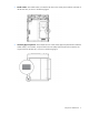
• Model number—The model number is located on the door to the control panel inside the cold aisle of the HP POD 20c, as shown in the following figure. • CSC Safety Approval placard—Each HP POD 20c has a CSC Safety Approval placard that includes the model number, serial number, and proof load. The CSC Safety Approval placard is located on the cargo end of the HP POD 20c, as shown in the following figure.
Life safety component identification Item Component Description 1 Exit sign locations Indicates the location of an exit 2 EPO strobe Red—An EPO event occurred and the HP POD 20c shut down.
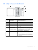
Electrical power component identification Front view shown Item Component Description 1 Demarcation box* Customer communication connection point for the following components: • • • ECS Security Phone 2 Fire box* Connection location for fire emergency and VESDAnet signals 3 380-415 VAC Y, 3-phase, 400 A Feed A and B power for IT critical loads busways and house power *The demarcation box and the fire box are communication data points that are provided on the POD by HP.
External panel labels Front view shown Item Electrical safety label Description 1 Danger sign Provides a reminder to users that the electrical panels must be accessed only by authorized personnel 2 Disconnect label Provides the order for disconnecting the electrical panels 3 Caution Cautions users about isolating power from the HP POD 20c.
Item Electrical safety label Description 2 Lists the layout and designation for all circuit breakers 3 Panel schedule/circuit breaker table Fuse type table 4 Wire color code Lists the 380-415 Y/200-240 V color codes: Lists all fuse types and sizes • • • • • Purple/Brown—Phase A/L1 Purple/Orange—Phase B/L2 Purple/Yellow—Phase 3/L3 Purple/White—Neutral Green and yellow—Equipment ground Control cabinet component identification Item Component Description 1 An early warning laser scan smoke det
HP POD 20c racks The HP POD 20c contains a total of 10 IT racks. CAUTION: If any racks contain empty RU space, use the HP POD 20c filler panels to maintain the efficiency of the HP POD 20c thermal system. Filler panels are available from HP in 10-pack quantities (part number AQ682A) and 100-pack quantities (part number AS993A). For more information about racks and network cabling, see the HP Performance Optimized Datacenter Networking Guide.
Life safety systems Life safety overview The HP POD 20c has multiple life safety systems that all work together to protect the HP POD 20c equipment and personnel.
For the location of EPO buttons, see "Life safety component identification (on page 10)." The EPO system must be reset before you can power up and restart the HP POD 20c. To reset the EPO system: 1. Verify that the key control for the EPO mode is in the Armed position. 2. Press the white EPO Reset button. If you triggered the EPO system manually, you must reset the EPO button that you pressed to the Active position.
Item Component 7 EPO reset button Indicator Color Description — Resets the EPO system when pressed EPO modes The EPO system has three operating modes: • Armed—The EPO system is armed and operational. • Test—The EPO system is in test mode and does not initiate during events that normally trigger an EPO. • Bypass—The EPO system is non-operational and does not initiate during events that normally trigger an EPO.
Manually activating a fire pull does the following: • Activates the POD fire alarm system horn and strobe lights • Triggers a fire alarm signal to the BMS in the fire box (on page 68) and activates a 30-second delay before releasing the fire suppression agent IMPORTANT: The fire suppression abort button will not delay the release of the fire suppression agent if a manual fire pull is initiated. All personnel should evacuate immediately.
The orange VESDA conduits that run throughout the HP POD 20c include inlets for smoke sampling. The VESDA uses a high-efficiency aspirator to continuously draw in air from the HP POD 20c and circulate the air through a dual-stage filter: • Stage 1—Dust and dirt are removed from the air sample. • Stage 2—Remaining contaminants in the air sample are removed with an ultra-fine filter.
• Acknowledge button • Alarm Silence button • System Reset button The fire system and panel are tested by the local certified fire system supplier and witnessed and certified by the local AHJ or fire marshal. The fire system operator panel requires regular maintenance and service. For more information on the fire system operator panel component, see the Operation and Maintenance Manual for the HP Performance Optimized Datacenter 20c.
Power, electrical, and controls Site electrical system To ensure a complete and safe integration of the HP POD solution with your facility, HP requires that you complete the following actions for the installed electrical system prior to the installation of the HP POD solution: • Short circuit analysis • Arc flash study • Circuit breaker coordination study These actions must be performed for all associated parts of the electrical power train.
A certified electrician must test and verify that the HP POD 20c is properly grounded. Lightning protection The HP POD 20c structural and internal components are bonded together. A common Grounding Electrode Conductor Connection point is provided. Proper bonding and grounding of the HP POD 20c minimizes the effects of a lightning strike. A surge protection device is provided on the HP POD 20c input connection to protect the HP POD 20c electrical system from voltage transients.
Capacities HP POD 20c capacity limitations The capacity limitations for the HP POD 20c are separated into two categories: electrical power and mechanical cooling capacities. Both of these categories are interdependent and must be considered in conjunction with the overall customer requirements. Electrical and mechanical cooling capacities Feature Specification Critical IT electrical connections 2 x 400 A feeders at 380-415 VAC Y, 3-Phase, at 50-60 Hz with equipment ground conductors 2 x 3 in (5.1 x 7.
The power feed access is 7.6 cm (3 in). Power feeders are sized in accordance with national, regional, and local regulations. Maintain NEMA 3R power when installing power. Electrical panels WARNING: To avoid the risk of personal injury or loss of life, all personnel must comply with PPE requirements when opening or working inside areas of the HP POD 20c that are marked as hazardous voltage, in accordance with national, regional, and local regulations.
Power distribution: Electrical busway system The rack power distribution system for the HP POD 20c is protected by electrical circuit breakers located on the end of the HP POD 20c.
Wire color Description Green or green and yellow • • • Equipment grounding conductor Bonding conductor Earth ground 380-415 V wiring system—Power required for electrical busway feeders Wire color Description Brown and violet A Phase Orange and violet B Phase Yellow and violet C Phase White and violet Neutral Green or green and yellow • • • Equipment grounding conductor Bonding conductor Earth ground Control cabinet power components Item Component Description 1 S2 power UPS Provides b
Electrical busways The electrical busway is a modular, overhead electrical distribution system that supplies power to the HP POD 20c IT loads. The HP POD 20c includes two busways and each busway can support 200 A. Top view shown The HP POD 20c electrical busways can be configured for non-redundant power or redundant power. The HP POD 20c can be installed as a single source 1N load by providing all required feeders from one common power source and from common switchboards and transformers.
Redundant power installation (2N load)—Each busway is powered through parallel power paths from independent power feeds. Drop boxes The internal electrical busways provide a location to connect each of the drop boxes, which then power the PDUs. Stagger the drop boxes on the electrical busways by connecting one drop box to busway #1 and connecting the next drop box to busway #2. A staggered configuration enables load balancing with the rack equipment and is necessary to ensure redundancy.
• To disable power to a single busway, open the appropriate breaker for that busway on the corresponding electrical busway panel on the HP POD 20c exterior. • To disable power to all racks, open the breaker for each busway on the corresponding electrical panel on the HP POD 20c exterior. Power configurations IMPORTANT: Different PDUs can alter the average power capacity per rack.
A light switch is located at every personnel door. For more information on light switch locations, see "Life safety component identification (on page 10)." All six lights are connected to battery backup power, keeping the interior of the HP POD 20c illuminated during a power outage or emergency. For more information on lighting, see the HP Performance Optimized Datacenter 20c Maintenance and Service Guide.
Environmental control system Environmental control system overview The ECS developed for the HP water-cooled POD is a stand-alone control system that requires no external connections with an external site system, BMS, public or private Internet sites, cloud, or wireless system to properly control the POD operation. The ECS includes Modbus TCP/IP connections through which a variety of data can be retrieved.
By connecting your HP POD 20c to a BMS system, you can monitor the various parameters and alarms. For more information, see "Navigating the ECS interface (on page 39)." The complete list of parameters and alarms that can be monitored will be discussed with your facilities personnel. IMPORTANT: If your site does not have a BMS, HP POD 20c ECS data can be sent to and viewed from a set IP address. Communication occurs through an Ethernet cable that is connected to the demarcation box (on page 67).
Top view shown Temperature sensors The values from the temperature sensors are calculated together to determine an average temperature for each aisle of the HP POD 20c. Cold aisle temperature sensors Three temperature sensor probes are located in the cold aisle of the HP POD 20c. These temperature sensors monitor the temperature in various locations throughout the cold aisle and report data to the ECS.
Top view shown Heat exchanger temperature sensors There are two contact temperature sensors per heat exchanger. One temperature sensor is located on the inlet supply piping and one temperature sensor is located on the outlet return piping. These sensors measure water temperature and report data to the ECS.
Managing the ECS from the HP POD 20c The ECS interface is viewed directly from the ECS screen on the control cabinet door in the cold aisle. For more information, see "ECS touchscreen and EPO indicators (on page 16)." To access the ECS using a host computer, connect an Ethernet cable between the host computer and the designated ECS jack on the back of the door inside of the control cabinet. Configuring the ECS 1. Connect a host computer to the ECS.
a. Select Start>Control Panel>Network Connections. b. Double-click Local Area Connection. c. Select Internet Protocol (TCP/IP). d. Click Properties. e. Select Use the following IP address.
f. Enter the new IP address. Be sure to specify an IP address in the same network group as the ECS controller. By default, the ECS controller uses 192.168.20.1. The IP address for your computer can include any number in the group from 2 to 254. g. Click OK. 3. Click OK to save changes and close the TCP/IP Properties screen. 4. Click OK to close the Local Area Connections Properties screen.
4. Click Connect. Locating the ECS IP addresses IMPORTANT: The ECS has three NIC addresses: 10.10.10.1, 10.10.10.2, and an IP address that is set up by the customer for external communication. The PLC must be connected to locate the IP address for each NIC. For more information, see "Managing the ECS from the HP POD 20c (on page 35)." To locate the ECS IP address: 1. Select Start>Run. 2. Enter ipconfig. The IP address appears. -or1. Select Start>Network and Sharing Center. 2.
Password protection The ECS has two levels of security: • Customer • Service The following screens are available using the customer-level password: • Overview screen (on page 42) • Status overview screen (on page 44) • Basic System Configuration screen (on page 45) The following screens require the service-level password: CAUTION: Making changes to the ECS in the service-level area can cause the cooling system components to fail.
Environmental control system 40
Item Button Description 1 Zone (#) power supply status Navigates directly to the Power Details screen for the specified Zone (#) 2 Fan Bank Output Navigates directly to the Fan Control Detail screen for the specified Zone (#) 3 Enter Password • • 4 System status/reset Alarms Enter customer level password—Navigates directly to the Basic System Configuration screen (on page 45) Enter service level password—Navigates directly to the Advanced System Configuration screen (on page 51) or the Controll
Overview screen The Overview screen appears upon activation of and displays an overview of the ECS components and the status of each component.
The Overview screen displays the following information. Information Description Average voltage, current, and power drawn on the A and B busways Indicates electrical usage Fan speed Indicates the fan bank speed percentage Hot aisle temperature Indicates the average temperature in the hot aisle System status Indicates the status of the ECS system: • • Green—All components within the ECS system are operating within normal parameters, and there are no active ECS alarms.
Status Overview screen The Status Overview screen displays the status of all system component alarms. For more information about the alarms, see "ECS alarms (on page 59).
The ECS component icon colors indicate the component status: • Green—There are no alarm conditions and the component is operating within normal parameters. • Red—An alarm condition for that component exists or the component failed. Basic System Configuration screen IMPORTANT: The ECS parameters must be set by qualified service personnel only.
The Basic System Configuration screen displays the basic alarm parameters, fan controls, and the definition of units. The configured parameters are only used to trigger an ECS alarm. The parameters listed on this screen do not configure the cooling system.
You can select and configure the following parameters: • Cold aisle temperature alarm parameters • Hot aisle temperature alarm parameters • Humidity alarm parameters • Differential pressure alarm parameters • Chilled water supply pressure parameters • Chilled water supply temperature parameters • Chilled water return temperature parameters • Type of units displayed You must select Save to store the parameter changes in the system configuration file.
3. Select Save to store the new parameters in the system configuration file. To configure the cold aisle high temperature alarm parameters: 1. Select Cold Aisle High Alarm Temperature. A keypad appears. 2. Enter a temperature alarm parameter. 3. Select Save to store the new parameters in the system configuration file. Configuring the hot aisle temperature alarm parameters The current temperature parameters appear on the related buttons. To configure the hot aisle low temperature alarm parameters: 1.
2. Enter a temperature alarm parameter. 3. Select Save to store the new parameters in the system configuration file. To configure the chilled water return high temperature alarm parameters: 1. Select the Chilled Water Return High Alarm Temperature. A keypad appears. 2. Enter a temperature alarm parameter. 3. Select Save to store the new parameters in the system configuration file. Configuring the humidity alarm parameters The current relative humidity parameters appear on the related buttons.
A keypad appears. 2. Enter a differential pressure alarm parameter. 3. Select Save to store the new parameters in the system configuration file. To configure the high differential pressure filter parameters: 1. Select Differential Pressure Filter High Alarm. A keypad appears. 2. Enter a differential pressure alarm parameter. 3. Select Save to store the new parameters in the system configuration file.
2. Select the dimensions (metric or imperial) to be displayed throughout the ECS interface. 3. Select Save. Setting the fan controls for each fan control zone The current fan speed appears on each fan control zone. HP recommends leaving the fans in AUTO mode during normal operation. To configure the fan speed: 1. Select the Auto/Manual in the fan control zone you want to change. 2. If you are setting the fan to Manual mode, select the fan speed (0-4) by pressing the corresponding number. 3.
The Advanced System Configuration screen displays fan current setpoints, calibration options, and other details about the HP POD 20c.
Perform the following tasks on this screen: • Configure the IP address for each power meter • Control the fans in each zone • Control the valve • Configure the HP POD 20c serial number • Configure the switchboard serial number • Calibrate the flowmeter • Calibrate the chilled water and differential pressure sensors • Enable or disable power measurement You must select Save to store the parameter changes in the system configuration file.
2. Enter a fan current tolerance setpoint. 3. Select Save to store the new parameters in the system configuration file. Fan current hysteresis The fan current hysteresis parameters appear on the related buttons. To configure the fan current hysteresis parameters: 1. Select Fan Current Hysteresis. A keypad appears. 2. Enter a fan current hysteresis setpoint. 3. Select Save to store the new parameters in the system configuration file.
8. Select Calibrate Chilled Water Pressure Sensor when the button reads Available. 9. Enter the original calibration factor that you noted down in step 5. 10. Select Save to exit. Calibrating the differential pressure sensors This option is available only when all fans and the IT load are powered off and there is no air flowing inside the HP POD 20c. To calibrate the chilled water pressure sensors: 1. Power down the POD. For more information, see "Power down procedure (on page 73)." 2.
Setting the HP POD 20c serial number If multiple HP POD 20c units are connected to the same facility BMS, enter each HP POD 20c serial number to monitor and display each HP POD 20c ECS independently through the facility BMS. To set the HP POD 20c serial number in the ECS: 1. Select POD S/N. A keypad appears. 2. Enter the HP POD 20c serial number. For more information, see "Parts and part number identification (on page 8)." 3. Select Save to store the new parameters in the system configuration file.
The Controller Settings screen displays the control setpoints for each major system component.
You can set the following configuration options: • High, medium, and low fan step offsets • Step shift and differential pressure control delays • Initial start time • Temperature and pressure setpoints • Temperature and pressure time constants You must select Save to store the parameter changes in the system configuration file. If you do not save your changes, the old parameters stored in the configuration file reload when the system starts.
Configuring the fan step offset The fan step offset parameters appear on the related buttons. To configure the fan step offset parameters: 1. Select the appropriate (High, Medium or Low) Fan Step Offset button. A keypad appears. 2. Enter a fan step offset setpoint. 3. Select Save to store the new parameters in the system configuration file. ECS alarms The alarms pertaining to the health of the HP POD 20c and its components are relayed through the ECS.
Safety and security alarms Alarms pertaining to the safety of the HP POD 20c are (optionally) relayed through your building fire and security dispatch. Alarm Meaning Solution Fire alarm* The HP POD 20c detected a fire. Activate the EPO. Follow the emergency procedures for your facility. Security alarm (optional) A security breach occurred. Follow the emergency procedures for your facility. EPO The EPO system activated and the HP Follow the emergency procedures for your POD 20c shut down. facility.
Cooling system HP POD 20c cooling system theory of operation CAUTION: Using contaminated supply water can cause decreased cooling capacity or disruption in service. The supply water must meet the guidelines stated in the HP Performance Optimized Datacenter 20c Site Preparation and Requirements Guide. Damage caused by contaminated supply water is not covered by the warranty.
Water quality requirements and specifications The following are the water quality requirements and specifications: • Closed-loop water must not contain any lime scale deposits or loose debris. • The temperature of the chilled water supplied to the HP POD 20c must be 12ºC to 24ºC (55ºF to 75ºF). CAUTION: Freezing water can cause a blockage and damage to the unit. In outside locations that are subject to freezing temperatures, an additive such as glycol might be necessary to lower the freezing point.
Feature Specification HP POD 20c pressure drop 172.4 kPa (25 psi) HP POD 20c water flow rate 454 lpm (120 gpm) Chilled water supply and return connections Two DIN PN16 DN80 flanges Cooling system components Each of the three heat exchanger area access hatches are rated NEMA 3R for outdoor use. The exterior of the hatches are coated with a durable finish to protect against corrosion. The access hatches are located on the roof of the POD.
Side view shown Item Component Description 1 Heat exchanger Use chilled facility water to cool the air in the HP POD 20c 2 Drain pan sensor Detects excessive amounts of condensate in the drain pan and sends an alarm signal to the ECS 3 Drain pan Collects and directs heat exchanger condensate to the condensate drain 4 Condensation drain Removes condensation from the drain tray to the exterior of the HP POD 20c 5 Header drain pan Provides leak detection for the chilled water supply and the c
Depending on the IT equipment installed in your HP POD 20c, you can choose to change both default parameters to improve the overall efficiency of your system. To discuss the effects of changing these parameters for your specific HP POD 20c, contact HP ("HP contact information" on page 80).
The HP POD 20c has one heat exchanger condensate drain. IMPORTANT: You might need to connect the HP POD 20c drain directly to the local storm or sanitary drain, depending on the local jurisdiction. If your HP POD 20c is located indoors, you can connect to an external drain line. If your HP POD 20c is located outdoors, the water drains out the back of the HP POD 20c. HP recommends connecting the condensate drain on the HP POD 20c to a facility drain to prevent collection of water near the HP POD 20c.
IT networking and communications Networking Connecting the HP POD 20c to the facility network is a vital part of ensuring the functionality of the various communication systems. See the HP Performance Optimized Datacenter Networking Guide for more information. All connections are the responsibility of the customer. For configuration and installation instructions, consult with HP. Connection portals There are networking and connection portals located on the cargo end of the HP POD 20c.
End view shown You must make the connections between the facility and the HP POD 20c. For configuration and installation instructions, consult with HP. Fire box The communication connections between the fire system and the HP POD 20c are made through the fire box. End view shown You must make the connections between the facility and the HP POD 20c. For configuration and installation instructions, consult with HP.
Optional components Fire protection system The fire protection system is a HP POD 20c self-contained system with no connection to your ECS. The fire protection system consists of FM200, a clean agent fire suppressant, eliminating the need for additional water to be connected to the HP POD 20c. Humidifier The humidifier option maintains the humidity in the HP POD 20c within a set range according to ASHRAE standards.
Power up procedure Standard HP POD 20c power up procedure This procedure is for your reference only and assumes that the POD was fully commissioned and powered up by HP before being turned over to you. Before beginning the power up procedures in this section, verify that the POD is not in operation and that the internal ambient temperature of the POD is greater than 10ºC (50ºF).
Site chilled water 1. Open the POD supply chilled water isolation valve. 2. If necessary, vent the air from the chilled water return header. 3. Open the POD return chilled water isolation valve. 4. Verify that audible flow noises are present. ECS and EPO Verify the following on the ECS screen and EPO indicators: • The ECS panel is operational and displaying the user interface. • The POD lighting is operational. • The EPO system is set to Armed (White) or Bypass (Green). POD operation 1.
Cold weather power up checklist Site electrical Open (verify open) all site POD feeder supply breakers. POD mechanical Open (verify open) POD chilled water return butterfly isolation valve. POD electrical • Hot aisle—Verify that all IT power drop box breakers on the power tap boxes are open. • Cold aisle a. Close all breakers and fuses within the control cabinet. b. Close and latch the ECS cabinet with the supplied T-handle. c. Position the EPO system (on page 15) to Armed (White) or Bypass (Green).
ECS and EPO Verify the following on the ECS screen and EPO indicators: • The ECS panel is operational and displaying the user interface. • The POD lighting is operational. • The EPO system is set to Armed (White) or Bypass (Green). POD heating procedure 1. On the ECS screen, verify that all system components are operational (green) and there are no faults. 2. On the ECS screen, verify that the POD chilled water flow rate has been established on the flow rate indicator. 3.
4. Close the POD return chilled water isolation valve. 5. Close the POD supply chilled water isolation valve. 6. Open the POD main power feed breakers. 7. Unlock the POD power cabinets A and B. 8. Open all breakers in the POD power cabinets A and B. The HP POD 20c is now powered down and all breakers are ready for standard or cold weather power up.
Specifications General HP POD 20c specifications Features Specifications Overall dimensions • • • Weight1 Empty—7,711 kg (17,000 lb) Maximum fully loaded—22,680 kg (50,000 lb) Maximum power2 288 kW HP POD 20c Power input voltage 380-415 VAC Power distribution3 2 x 200 A electrical busways Maximum rack quantity 10 racks Rack Units (RU) per rack 50 RU Rack Units (RU) total 500 RU Average capacity per rack (kW) 30 kW Peak rack capacity 69 kW Voltage to rack 200-240 VAC Minimum quantity
Fire alarm panel connections The electrical layout of the fire alarm system is as described in the schematic drawing supplied with the HP POD 20c. Water specifications The following table describes the chilled water system specifications for the HP POD 20c. Feature Specification Facility input temperature to the HP POD 20c 12º to 24ºC (55º to 75ºF) Working pressure 1,034 kPa (150 psi) HP POD 20c pressure drop 172.
Feature Specification Operating humidity • • 0% to 100% external 10% to 90% non-condensing internal Non-operating humidity* • • 5% to 95% relative non-condensing 39ºC (102ºF) maximum wet bulb temperature Operating altitude -76.2 m to 3,048 m (-250 ft to 10,000 ft) Non-operating altitude -76.2 m to 9,144 m (-250 ft to 30,000 ft) *For non-operating specifications, consider the temperature of computer and IT equipment inside the HP POD 20c.
Maintenance Periodic maintenance Perform periodic inspections to ensure that the HP POD 20c continues to perform according to design parameters. During periodic inspections, pay special attention to electrical connections and wiring. For more specific maintenance information, see the HP Performance Optimized Datacenter 20c Maintenance and Service Guide. Sample HP POD 20c maintenance schedule For detailed maintenance information and schedules, consult with HP services.
Support and other resources China (North and South) contact information Care Pack and product consultation If you have purchased a Care Pack (service upgrade), see the Support & Drivers website (http://www8.hp.com/us/en/support-drivers.html). If the problem cannot be resolved at the website, call 1-800-820-2255 (landlines only) or 1-400-820-2255 (mobile). For more information about Care Packs, see the HP website (http://pro-aq-sama.houston.hp.com/services/cache/10950-0-0-225-121.html).
Contacting HP Before you contact HP Be sure to have the following information available before you call HP: • Active Health System log Download and have available an Active Health System log for 3 days before the failure was detected. For more information, see the HP iLO 4 User Guide or HP Intelligent Provisioning User Guide on the HP website (http://www.hp.com/go/ilo/docs).
Glossary AHJ authority having jurisdiction BMS building management system branch circuit The conductors and components following the last overcurrent protective device protecting a load. control circuit A circuit that carries the electric signals directing the performance of a controller, and which does not carry the main power circuit. control transformer A transformer whose secondary supplies power to control circuit devices only (excluding loads).
fuse, branch circuit type A fuse of Class CC, G, H, J, K, L, R, and T. These fuses are able to provide branch circuit protection. fuse, supplementary type Miscellaneous type and miniature type fuses. These fuses are able to provide supplementary protection only. overload protection Protection required for motor circuits that will operate to prohibit excessive heating due to running overloads and failure to start.
Documentation feedback HP is committed to providing documentation that meets your needs. To help us improve the documentation, send any errors, suggestions, or comments to Documentation Feedback (mailto:docsfeedback@hp.com). Include the document title and part number, version number, or the URL when submitting your feedback.
Index A E access 69 advanced system configuration 51 alarms, ECS 59 arc flash safety 24 ECS alarms 59 ECS components 31 ECS configuring 35 ECS connections 34 ECS interface 39 ECS panel 16 ECS parameters, chilled water return supply 48 ECS parameters, chilled water supply 50 ECS parameters, chilled water supply temp 48 ECS parameters, cold aisle temperature 47 ECS parameters, differential pressure 49 ECS parameters, hot aisle temperature 48 ECS parameters, humidity 49 ECS status 44 ECS, configuring 35 ECS
fire suppression 7, 19 flow meter, calibrating 54 H HP POD 20c components 8 HP POD 20c racks 14 HP POD cooling 61 humidifier 69 humidity alarm parameters 49 humidity sensor 32 power feeders 23 power safety 21 power up checklist 70, 72 power up procedure 70, 71 power, rack 29 pressure sensors 32 R rack specifications 76 requirements, water quality 62 L S life safety components 10 life safety overview 15 life safety systems 15 lighting 29 lightning protection 22 locating the ECS IP address 38 logging in
work space, lighting 29 Index 86