HP Performance Optimized Datacenter 20c User Guide - North America Abstract This guide is intended for the person who operates and maintains the HP Performance Optimized Datacenter 20c (HP POD 20c).
© Copyright 2013 Hewlett-Packard Development Company, L.P. The information contained herein is subject to change without notice. The only warranties for HP products and services are set forth in the express warranty statements accompanying such products and services. Nothing herein should be construed as constituting an additional warranty. HP shall not be liable for technical or editorial errors or omissions contained herein. Confidential computer software.
Contents Overview ..................................................................................................................................... 6 Before you begin.......................................................................................................................................... 6 Operator safety............................................................................................................................................ 6 Component safety ..........................
HP POD 20c lighting .................................................................................................................................. 32 Environmental control system ........................................................................................................ 33 Environmental control system overview ......................................................................................................... 33 Using the ECS ...........................................................
Rack specifications ..................................................................................................................................... 74 Thermal and air flow performance ............................................................................................................... 74 Environmental specifications ........................................................................................................................ 74 Maintenance .........................................
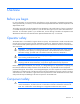
Overview Before you begin For more information on site requirements, specifications, power requirements, management requirements, and supported facility connections, see the HP Performance Optimized Datacenter 20c Site Preparation and Requirements Guide. This guide is part of the core documentation for the HP POD 20c. The actual location of various components or included subsystems and their operation in your HP POD 20c might vary from what is described in this document.
CAUTION: Electrostatic discharge might damage electronic components. Be sure that you are properly grounded (earthed) by wearing approved grounding straps before beginning any installation procedure or repair. CAUTION: If any racks contain empty RU space, use the HP POD 20c filler panels to maintain the efficiency of the HP POD 20c thermal system. Filler panels are available from HP in 10-pack quantities (part number AQ682A) and 100-pack quantities (part number AS993A).
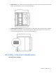
Component identification Structural component identification The HP POD 20c documentation frequently refers to the specific components of the HP POD 20c as shown in the following figure and described in the following table.
• Model number—The model number is located adjacent to the door to the control panel inside the cold aisle of the HP POD 20c, as shown in the following figure. • CSC Safety Approval placard—Each HP POD 20c has a CSC Safety Approval placard that includes the model number, serial number, and proof load. The CSC Safety Approval placard is located on the cargo end of the HP POD 20c, as shown in the following figure.
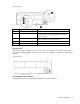
Top view shown Item Component Description 1 EPO button Disconnects the HP POD 20c from main power feeds 2 Fire alarm manual pull* Enables manual initiation of the fire system, which includes activating the interior fire strobe light and the optional fire suppression system 3 Fire suppression abort button* Aborts the fire suppression system. A fire suppression abort button is located next to the personnel door.
Top view shown External life safety components Side view shown Item Component Description 1 EPO strobe RED—An EPO event occurred and the HP POD 20c shut down 2 EPO button (optional) Disconnects the HP POD 20c from main power, activates the red EPO indicator on the control cabinet door, and activates the red EPO strobe on the HP POD 20c exterior Component identification 11
Electrical power component identification Front view shown Item Component Description 1 Demarcation box* Customer communication connection point for the following components: • • • • ECS Access control Phone Convenience power hook up 2 Transformer cabinet Contains two 480/415 VAC transformers 3 House and critical power cabinet Contains A and B house power and critical IT power components *HP provides the demarcation box as a communication data point on the POD.
Front view shown External panel labels Front view shown Item Electrical safety label Description 1 Danger sign Provides a reminder to users that the electrical panels must be accessed only by authorized personnel 2 Disconnect label Provides the order for disconnecting the electrical panels 3 Caution Cautions users about isolating power from the HP POD 20c.
Front view shown Item Electrical safety label Description 1 Input power Lists the input power information 2 Lists the layout and designation for all circuit breakers 3 Panel schedule/circuit breaker table Fuse type table 4 Wire color code Lists the 380-415 Y/200-240 V color codes: Lists all fuse types and sizes • • • • • Brown/Violet—Phase A/L1 Orange/Violet—Phase B/L2 Yellow/Violet—Phase 3/L3 White/Violet—Neutral Green and yellow—Equipment ground Control cabinet component identification C
Item Component Description 1 An early warning laser scan smoke detection unit 3 VESDA air sampling smoke detection unit Access control transformer panel EPO panels 4 Access control panel Monitors access control and door positions 5 ECS panel Relays for the ECS control, ECS communications, I/O connections, and terminal block connections 6 Fire alarm panel • 2 120 VAC transformer for the access control system Connections for the EPO system • Controls all fire systems within the HP POD 20c,
Life safety systems Life safety overview The HP POD 20c has multiple life safety systems that work together to protect the HP POD 20c equipment and personnel.
For the location of EPO buttons, see "Life safety component identification (on page 9)." The EPO system must be reset before you can power up and restart the HP POD 20c. To reset the EPO system: 1. Verify that the key control for the EPO mode is in the Armed position. 2. Press the white EPO Reset button. If you triggered the EPO system manually, you must reset the EPO button that you pressed to the Active position.
EPO modes The EPO system has three operating modes: • Armed—The EPO system is armed and operational. • Test—The EPO system is in test mode and does not initiate during events that normally trigger an EPO. • Bypass—The EPO system is non-operational and does not initiate during events that normally trigger an EPO. EPO accidental activation To help prevent accidentally pressing the EPO button and activating the EPO system, each EPO button is covered with a clear Lexan cover.
• Level 2—Smoke concentration reaches the second setpoint, and the VESDA system indicates that a fire exists in the HP POD 20c and sends an activation signal to the fire suppression system. IMPORTANT: The VESDA filter must be changed regularly to ensure accurate smoke detection readings. For more information about changing the VESDA filters, see the HP Performance Optimized Datacenter 20c Maintenance and Service Guide.
CAUTION: The POD fire suppression system is manufacturer designed, engineered, and installed to comply with national standards. However, HP does not certify that the installed fire suppression system meets all local jurisdictional requirements. Compliance with local codes is your responsibility, and includes specific local requirements for initial and periodic inspections, certifications, and maintenance.
Fire suppression system stages Beats per minute Description Personnel actions Warning 20 An alarm condition exists Personnel may investigate Pre-discharge 120 Post-discharge Steady Countdown to fire suppression Personnel should evacuate agent has started Fire suppression agent is released Personnel should not enter, contact local AHJ The fire system operator panel indicates which initiation sequence has begun with indicator lights and a panel alarm.
o Standard hardware—Door strikes o Optional hardware—Electric door strikes Each personnel door includes a standard panic bar to ensure safe exit. The optional egress hardware included in the HP POD 20c (including electric panic bars, electric strikes, and magnetic locks) are tied to the fire alarm to enable uninhibited egress in the event of an emergency.
Power, electrical, and controls Site electrical system To ensure a complete and safe integration of the HP POD solution with your facility, HP requires that you complete the following actions for the installed electrical system prior to the installation of the HP POD solution: • Short circuit analysis • Arc flash study • Circuit breaker coordination study These actions must be performed for all associated parts of the electrical power train.
A certified electrician must test and verify that the HP POD 20c is properly grounded. Lightning protection The HP POD 20c structure and internal components are all bonded together. A common Grounding Electrode Conductor Connection point is provided. Proper bonding and grounding of the HP POD 20c minimizes the effects of a lightning strike. A surge protection device is provided on the HP POD 20c input connection to protect the HP POD 20c electrical system from voltage transients.
Capacities HP POD 20c capacity limitations The capacity limitations for the HP POD 20c are separated into two categories: electrical power and mechanical cooling capacities. Both of these categories are interdependent and must be considered in conjunction with the overall customer requirements. Electrical and mechanical cooling capacities Feature Specification Critical IT electrical connections 2 x 400 A feeders at 480VAC Delta, 3-Phase, 3-wire, with equipment ground conductors 2 x 4 in (5.1 x 10.
Hot aisle side view shown The top of each electrical panel has four 10.16 cm (4 in) welded couplings where the power feeders are connected. Power feeders are sized in accordance with NFPA 70 2008/2011 and any local or regional codes applicable to the installation site. Maintain NEMA 3R power when installing power.
Front view shown Item Component Description 1 Demarcation box* Customer communication connection point for the following components: • • • • ECS Access control Phone Convenience power hook up 2 Transformer cabinet Contains two 480/415 VAC transformers 3 House and critical power cabinet Contains A and B house power and critical IT power components *HP provides the demarcation box as a communication data point on the POD.
Front view shown Feature Specification Number of busways 2 Frequency 50-60 Hz Amps (per busway) 200 A Voltage (per busway) 415 VAC Grounding Copper Busway conductors 3-phase + neutral + equipment ground Panel schedules The panel schedule for each electrical panel is permanently affixed to the inside cabinet door of each electrical panel. Wire color code IMPORTANT: The use of UL-approved colored tape over another color of wire is only acceptable on wire sizes #2 and larger.
Wire color Description Brown and violet A Phase Orange and violet B Phase Yellow and violet C Phase White and violet Neutral Green or green and yellow • • • Equipment grounding conductor Bonding conductor Earth ground 480 V wiring system—Main power feeds Wire color Description Brown A Phase Orange B Phase Yellow C Phase Green or green and yellow • • • Equipment grounding conductor Bonding conductor Earth ground Electrical busways The electrical busway is a modular, overhead electrica
power source and from common switchboards and transformers. A 2N redundancy installation is configured by feeding the parallel power paths from independent power sources, switchboards, and transformers. • Non-redundant power installation (1N load)—Both main input connections to the HP POD 20c are powered from the same power feed. • Redundant power installation (2N load)—Each main input connection to the HP POD 20c is powered from parallel power paths from independent power feeds.
Side view shown Disabling power • To disable power to a single PDU, open the drop box breaker that powers the PDU, and then disconnect the PDU from the drop box. • To disable power to a single rack, open the drop box breakers that power each of the PDUs installed in that rack. • To disable power to a single busway, open the appropriate breaker for that busway on the corresponding electrical busway panel on the HP POD 20c exterior.
Feature Specification Rack type HP POD rack Max number of racks 10 Max U space per rack 50U Max U space per HP POD 20c 500U Server capacity 288 kW power capacity Average capacity per rack 28.
Environmental control system Environmental control system overview The ECS developed for the HP water-cooled POD is a stand-alone control system that requires no external connections with an external site system, BMS, public or private Internet sites, cloud, or wireless system to properly control the POD operation. The ECS includes Modbus TCP/IP connections through which a variety of data can be retrieved.
By connecting your HP POD 20c to a BMS system, you can monitor the various parameters and alarms. For more information, see "Navigating the ECS interface (on page 41)." The complete list of parameters and alarms that can be monitored will be discussed with your facilities personnel. IMPORTANT: If your site does not have a BMS, HP POD 20c ECS data can be sent to and viewed from a set IP address. Communication occurs through an Ethernet cable that is connected to the demarcation box.
Top view shown Temperature sensors The values from the temperature sensors are calculated together to determine an average temperature for each aisle of the HP POD 20c. Cold aisle temperature sensors Three temperature sensor probes are located in the cold aisle of the HP POD 20c. These temperature sensors monitor the temperature in various locations throughout the cold aisle and report data to the ECS.
Side view shown Heat exchanger temperature sensors There are two contact temperature sensors per heat exchanger. One temperature sensor is located on the inlet supply piping and one temperature sensor is located on the outlet return piping. These sensors measure water temperature and report data to the ECS.
Managing the ECS from the HP POD 20c The ECS interface is viewed directly from the ECS screen on the control cabinet door in the cold aisle. For more information, see "ECS EPO indicators (on page 17)." To access the ECS using a host computer, connect an Ethernet cable between the host computer and the designated ECS jack on the back of the door inside of the control cabinet. Configuring the ECS 1. Connect a host computer to the ECS.
b. Double-click Local Area Connection. c. Select Internet Protocol (TCP/IP). d. Click Properties. e. Select Use the following IP address. f. Enter the new IP address. Be sure to specify an IP address in the same network group as the ECS controller. By default, the ECS controller uses 192.168.20.1. The IP address for your computer can include any number in the group from 2 to 254.
g. Click OK. 3. Click OK to save changes and close the TCP/IP Properties screen. 4. Click OK to close the Local Area Connections Properties screen. Logging in remotely to the ECS Before you can log in remotely, you must do the following: • Add the PLC to a network • Obtain a username and password • Obtain the static IP address of the PLC. For more information, see "Locating the ECS IP addresses (on page 40)." Use the remote desktop application to log in to the ECS remotely: 1.
4. Click Connect. Locating the ECS IP addresses IMPORTANT: The ECS has three NIC addresses: 10.10.10.1, 10.10.10.2, and an IP address that is set up by the customer for external communication. The PLC must be connected to locate the IP address for each NIC. For more information, see "Managing the ECS from the HP POD 20c (on page 37)." To locate the ECS IP address: 1. Select Start>Run. 2. Enter ipconfig. The IP address appears. -or1. Select Start>Network and Sharing Center. 2.
Password protection The ECS has two levels of access control: • Customer • Service The following screens are available using the customer-level password: • Overview screen (on page 43) • Status Overview screen (on page 45) • Basic System Configuration screen (on page 45) CAUTION: Making changes to the ECS in the service-level area can cause the cooling system components to fail.
Item Button Description 1 Zone (#) power supply status Navigates directly to the Power Details screen for the specified Zone (#) 2 Fan Bank Output Navigates directly to the Fan Control Detail screen for the specified Zone (#) 3 Enter Password • • 4 System status/reset Alarms Enter customer level password—Navigates directly to the Basic System Configuration screen (on page 45) Enter service level password—Navigates directly to the Advanced System Configuration screen (on page 50) or the Controll
2. Enter your ECS password. 3. Click OK. Overview screen The Overview screen appears upon activation of and displays an overview of the ECS components and the status of each component. The Overview screen displays the following information.
Information System status Description Indicates the status of the ECS system: • • Green—All components within the ECS system are operating within normal parameters, and there are no active ECS alarms. Red—One or more of the ECS components is indicating an alarm condition.
Status Overview screen The Status Overview screen displays the status of all system component alarms. For more information about the alarms, see "ECS alarms (on page 56)." The ECS component icon colors indicate the component status: • Green—No alarm conditions exist and the component is operating within normal parameters. • Red—An alarm condition for that component exists or the component failed.
You can select and configure the following parameters: • Cold aisle temperature alarm • Hot aisle temperature alarm • Humidity alarm • Differential pressure alarm • Chilled water supply pressure • Chilled water supply temperature • Chilled water return temperature • Type of units displayed • Control the fans in each zone • Configure the IP address You must select Save to store the parameter changes in the system configuration file.
A keypad appears. 2. Enter a temperature alarm parameter. 3. Select Save to store the new parameters in the system configuration file. To configure the cold aisle high temperature alarm parameters: 1. Select Cold Aisle High Alarm Temperature. A keypad appears. 2. Enter a temperature alarm parameter. 3. Select Save to store the new parameters in the system configuration file. Configuring the hot aisle temperature alarm parameters The current temperature parameters appear on the related buttons.
To configure the chilled water return low temperature alarm parameters: 1. Select the Chilled Water Return Low Alarm Temperature. A keypad appears. 2. Enter a temperature alarm parameter. 3. Select Save to store the new parameters in the system configuration file. To configure the chilled water return high temperature alarm parameters: 1. Select the Chilled Water Return High Alarm Temperature. A keypad appears. 2. Enter a temperature alarm parameter. 3.
Configuring the differential pressure alarm parameters The current differential pressure filter parameters appear on the related buttons. To configure the low differential pressure filter parameters: 1. Select Differential Pressure Filter Low Alarm. A keypad appears. 2. Enter a differential pressure alarm parameter. 3. Select Save to store the new parameters in the system configuration file. To configure the high differential pressure filter parameters: 1.
Setting the dimensions of the ECS To set the dimensions of the ECS: 1. Select Dimensions. 2. Select the dimensions (metric or imperial) to be displayed throughout the ECS interface. 3. Select Save. Setting the fan controls for each fan control zone The current fan speed appears on each fan control zone. HP recommends leaving the fans in AUTO mode during normal operation. To configure the fan speed: 1. Select the Auto/Manual in the fan control zone you want to change. 2.
The Advanced System Configuration screen displays fan current setpoints, calibration options, and other details about the HP POD 20c.
To configure the fan current tolerance parameters: 1. Select Fan Current Tolerance. A keypad appears. 2. Enter a fan current tolerance setpoint. 3. Select Save to store the new parameters in the system configuration file. Fan current hysteresis The fan current hysteresis parameters appear on the related buttons. To configure the fan current hysteresis parameters: 1. Select Fan Current Hysteresis. A keypad appears. 2. Enter a fan current hysteresis setpoint. 3.
5. Note the current calibration factor. 6. Enter 0.1 as the new calibration factor. 7. Select OK. 8. Select Calibrate Chilled Water Pressure Sensor when the button reads Available. 9. Enter the original calibration factor that you noted down in step 5. 10. Select Save to exit. Calibrating the differential pressure sensors This option is available only when all fans and the IT load are powered off and there is no air flowing inside the HP POD 20c.
Setting the switchboard serial number To identify the switchboard connected to the HP POD 20c, set the switchboard serial number in the ECS: 1. Select Switchboard S/N. A keypad appears. 2. Enter the switchboard serial number. 3. Select Save to store the new parameters in the system configuration file.
The Controller Settings screen displays the control setpoints for each major system component. You can set the following configuration options: • Pressure P and I gain • Temperature P, I, and D gain • Temperature and pressure setpoints • Temperature and pressure time constants You must select Save to store the parameter changes in the system configuration file. If you do not save your changes, the old parameters stored in the configuration file reload when the system starts.
Item Description Controller hysteresis The degree to which the actual temperature can be different from the setpoint temperature before an alarm is set. ECS alarms The alarms pertaining to the health of the HP POD 20c and its components are relayed through the ECS. Alarm Meaning Solution Fan failure One of the fans is not working. See the HP Performance Optimized Datacenter 20c Maintenance and Service Guide or contact HP service if you are still within your service contract.
Alarm Meaning Solution Fire alarm* The HP POD 20c detected a fire. Activate the EPO. Follow the emergency procedures for your facility. Access control alarm (optional) An access control breach occurred. Follow the emergency procedures for your facility. EPO The EPO system activated and the HP Follow the emergency procedures for your POD 20c shut down. facility. *The fire alarm is relayed to your building fire and access control dispatch only if you have connected your facility to the fire box.
Cooling system HP POD 20c cooling system theory of operation CAUTION: Using contaminated supply water can cause decreased cooling capacity or disruption in service. The supply water must meet the guidelines stated in the HP Performance Optimized Datacenter 20c Site Preparation and Requirements Guide. Damage caused by contaminated supply water is not covered by the warranty.
Water quality requirements and specifications The following are the water quality requirements and specifications: • Closed-loop water must not contain any lime scale deposits or loose debris. • The temperature of the chilled water supplied to the HP POD 20c must be 12ºC to 24ºC (55ºF to 75ºF). CAUTION: Freezing water can cause a blockage and damage to the unit. In outside locations that are subject to freezing temperatures, an additive such as glycol might be necessary to lower the freezing point.
Feature Specification HP POD 20c pressure drop 172.4 kPa (25 psi) HP POD 20c water flow rate 454 lpm (120 gpm*) Chilled water supply and return connections Two DIN PN16 DN80 flanges Cooling system components Each of the three heat exchanger area access hatches are rated NEMA 3R for outdoor use. The exterior of the hatches are coated with a durable finish to protect against corrosion. The access hatches are located on the roof of the POD.
End view shown Item Component Description 1 Heat exchanger Uses chilled facility water to cool the air in the HP POD 20c 2 Drain pan sensor Detects excessive amounts of condensate in the drain pan and sends an alarm signal to the ECS 3 Drain pan Collects and directs heat exchanger condensate to the condensate drain 4 Condensation drain Removes condensation from the drain tray to the exterior of the HP POD 20c 5 Header drain pan Provides leak detection for the chilled water supply and the c
Top view shown Condensation management CAUTION: To maintain accurate environmental conditions inside the HP POD 20c, do not leave the HP POD 20c doors open during operation. The heat exchanger drip trays collect condensation that forms on the heat exchangers. This collected condensate drains out of the HP POD 20c through the heat exchanger condensate drain. HP recommends connecting the condensate drain on the HP POD 20c to a facility drain to prevent collection of water near the HP POD 20c.
Water from natural condensation forms. Condensation from the heat exchangers flows to one of the two condensation drains located at each end of the hot aisle. IMPORTANT: You might need to connect the HP POD 20c condensate drains directly to the local storm or sanitary drain, depending on the local jurisdictional requirements.
There should be no water in the header drain pan and the drain pan should always remain dry. Some amount of condensation water can always be expected in the heat exchanger drain pans. If an excessive amount of condensation water accumulates in a drain pan, an alarm is triggered and sent through the HP POD 20c ECS, indicating a possible leak. For more information on leak detection, see the HP Performance Optimized Datacenter 20c Maintenance and Service Guide.
IT networking and communications Networking Connecting the HP POD 20c to the facility network is a vital part of ensuring the functionality of the various communication systems. See the HP Performance Optimized Datacenter Networking Guide for more information. All connections are the responsibility of the customer. For configuration and installation instructions, consult with HP. Connection portals Networking and connection portals are located on the cargo end of the HP POD 20c. Each HP POD 20c has six 6.
• 120 VAC convenience outlet Front view shown You must make the connections between the facility and the HP POD 20c. For configuration and installation instructions, consult with HP.
Optional components Fire protection system The fire protection system is a HP POD 20c self-contained system, with no connection to your ECS. The fire protection system consists of 3M Novec 1230, a clean agent fire suppressant, eliminating the need for additional water to be connected to the HP POD 20c in case of a fire emergency. Humidifier The humidifier option maintains the humidity in the HP POD 20c within a set range according to ASHRAE standards.
Power up procedure Standard HP POD 20c power up procedure This procedure is for your reference only and assumes that the POD is fully commissioned and powered up by HP before being turned over to you. Before beginning the power up procedures in this section, verify that the POD is not in operation and that the internal ambient temperature of the POD is greater than 10ºC (50ºF).
Standard power up procedure Perform the following procedures in the exact order in which they are listed. Site electrical Close all POD site power feeder breakers and monitor for any effects that are not standard. Site chilled water 1. Open the POD supply chilled water isolation valve. 2. If necessary, vent the air from the chilled water return header. 3. Open the POD return chilled water isolation valve. 4. Verify that audible flow noises are present.
This process helps to ensure personnel safety during the electrical start up of the HP POD 20c. WARNING: To avoid risk of personal injury or loss of life, do not open an energized POD electrical cabinet without an energized work permit and appropriate PPE. Cold weather power up checklist Site electrical Open (verify open) all site POD feeder supply breakers. Site mechanical Verify that the POD supply and return isolation valves are closed.
Site chilled water 1. Open the POD supply chilled water isolation valve. 2. If necessary, vent the air from the chilled water return header. 3. Open the POD return chilled water isolation valve. 4. Verify audible flow noises are present. IMPORTANT: To allow the POD ambient temperature to be raised in a controlled manner, open the chilled water supply and return isolation valves to enable 454.
Power down procedure 1. Power down all IT equipment. 2. Open all POD power drop box breakers. 3. Monitor the system parameters and allow the POD to cool to an acceptable temperature. Be sure that the cold aisle temperature does not fall below 10°C (50°F.) 4. Close the POD return chilled water isolation valve. 5. Close the POD supply chilled water isolation valve. 6. Open the POD main power feed breakers. 7. Unlock the POD house power and critical IT power cabinets. 8.
Specifications General HP POD 20c specifications Features Specifications Overall dimensions • • • Height—3.05 m (10 ft) Length—6.10 m (20 ft) Width—2.43 m (7.
Fire alarm panel connections The electrical layout of the fire alarm system is as described in the schematic drawing supplied with the HP POD 20c. Water specifications The following table describes the chilled water system specifications for the HP POD 20c. Feature Specification Facility input temperature to the HP POD 20c 12º to 24ºC (55º to 75ºF) Working pressure 1,034 kPa (150 psi) HP POD 20c pressure drop 172.
Feature Specification Operating humidity • • 0% to 100% external 10% to 90% non-condensing internal Non-operating humidity* • • 5% to 95% relative non-condensing 39ºC (102ºF) maximum wet bulb temperature Operating altitude -76.2 m to 3,048 m (-250 ft to 10,000 ft) Non-operating altitude -76.2 m to 9,144 m (-250 ft to 30,000 ft) *For non-operating specifications, consider the temperature of computer and IT equipment inside the HP POD 20c.
Maintenance Periodic maintenance Perform periodic inspections to ensure that the HP POD 20c continues to perform according to design parameters. During periodic inspections, pay special attention to electrical connections and wiring. For more specific maintenance information, see the HP Performance Optimized Datacenter 20c Maintenance and Service Guide. Sample HP POD 20c maintenance schedule For detailed maintenance information and schedules, consult with HP services.
Contacting HP Before you contact HP Be sure to have the following information available before you call HP: • Active Health System log (HP ProLiant Gen8 or later products) Download and have available an Active Health System log for 3 days before the failure was detected. For more information, see the HP iLO 4 User Guide or HP Intelligent Provisioning User Guide on the HP website (http://www.hp.com/go/ilo/docs).
Regulatory information HP POD 20c regulatory compliance The HP POD 20c complies with the following regulatory standards.
• The HP POD 20c is designed for stationary installation outdoors in a Pollution Degree 3 environment, in restricted access locations, with field wiring terminals provided for permanent supply connections. • The HP POD 20c meets the following ratings. Feature Specification Category Rated Overvoltage Category III Protection Surge protection device Class Class1 Ambient temperature 2°C to 54°C (35.6°F to 129.
• the date of the transfer. Reports should be sent to Director, Office of Federal and State Materials and Environmental Management Programs, ATTN: GLTS, U.S. Nuclear Regulatory Commission, Washington, D.C. 20555-0001. For more information, see the Fact Sheet on Tritium EXIT Signs on the NRC website (http://www.nrc.gov/reading-rm/doc-collections/fact-sheets/fs-tritium.html).
Glossary AHJ authority having jurisdiction BMS building management system branch circuit The conductors and components following the last overcurrent protective device protecting a load. control circuit A circuit that carries the electric signals directing the performance of a controller, and which does not carry the main power circuit. control transformer A transformer whose secondary supplies power to control circuit devices only (excluding loads).
equipment A general term, including fittings, devices, appliances, luminaires, apparatus, machinery, and the like used as a part of, or in connection with, a modular data center. (Source: NEC.) fuse, branch circuit type A fuse of Class CC, G, H, J, K, L, R, and T. These fuses are able to provide branch circuit protection. fuse, supplementary type Miscellaneous type and miniature type fuses. These fuses are able to provide supplementary protection only.
RU rack units structure Enclosure of sufficient size to enable entry of personnel.
Documentation feedback HP is committed to providing documentation that meets your needs. To help us improve the documentation, send any errors, suggestions, or comments to Documentation Feedback (mailto:docsfeedback@hp.com). Include the document title and part number, version number, or the URL when submitting your feedback.
Index A access 67 advanced system configuration 50 alarms, ECS 56 arc flash safety 27 B basic system configuration 45 before you begin 6 before you contact HP 77 bonding 24 C capacity limitations 25 cold weather power up 69 component health 6 components 8 components, control cabinet 14 components, HP POD 20c 8 components, identification 8 condensation management 62 contact information 77 controlled access 67 controller settings 54 cooling 58 cooling the HP POD 20c 58 D differential pressure alarm paramet
M using the ECS 33 maintenance 76 maintenance schedule 76 W N water specifications 74 water temperature 58 navigating the ECS interface 41 networking 65 O optional components 67 overview screen 43 P panels 28 part numbers 8 password protected 41 periodic maintenance 76 power 23 power configurations 31 power down procedure 72 power feeders 25 power safety 23 power up procedure 68, 69 R rack specifications 74 regulatory compliance notices 78, 80 S safety and access control alarms 56 serial number 8,