HP Performance-Optimized Datacenter, 6 m (20 ft) User Guide Part Number 587018-001 June 2010 (First Edition)
© Copyright 2010 Hewlett-Packard Development Company, L.P. The information contained herein is subject to change without notice. The only warranties for HP products and services are set forth in the express warranty statements accompanying such products and services. Nothing herein should be construed as constituting an additional warranty. HP shall not be liable for technical or editorial errors or omissions contained herein. Confidential computer software.
Contents Site preparation and safety considerations ...................................................................................... 6 Before you begin.......................................................................................................................................... 6 Safety information ........................................................................................................................................ 6 Operator safety.........................................
Managing ECS settings from the HP POD ..................................................................................................... 32 Configuring the ECS ......................................................................................................................... 32 Logging in to the ECS ....................................................................................................................... 35 ECS alarms.....................................................................
Acronyms and abbreviations ........................................................................................................ 63 Index .........................................................................................................................................
Site preparation and safety considerations Before you begin For more information on site requirements, specifications, water quality requirements, power management requirements, and supported facility connections, see the HP Performance-Optimized Datacenter Site Requirements documentation. The location of various components or subsystems in your HP POD might vary from this documentation. For final placement specifications, see your operations and maintenance manual.
CAUTION: All customer supplied water fittings must be composed of carbon steel, stainless steel, or copper. Do not use cast iron, aluminum, or PVC fittings. CAUTION: During operation, avoid leaving the HP POD doors open, to maintain accurate environmental conditions inside the HP POD. CAUTION: If the HP POD is located outdoors, do not work in the hot aisle during inclement weather. If the chilled water stops flowing into the HP POD: 1. Turn off IT equipment. 2.
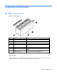
Component identification HP POD components HP POD external components Item Component Description 1 Rear entrance doors Enable access to the rear of the rack-mounted components 2 Fan units Circulate the cool air throughout the HP POD 3 Heat exchangers Use chilled water to cool the air 4 Electrical busway end feeds Provide main source of power distribution throughout the HP POD 5 Front entrance door Enables access to the front of the rack-mounted components 6 Drain lines* Collect water fr
If any of the racks within the HP POD contain empty U space, you must use the HP POD Filler Panel to avoid compromising the integrity of the hot and cold aisle temperatures. Filler panels are available from HP in 10-pack quantities (AQ682A) and 100-pack quantities (AS993A). HP POD emergency components The actual location of various components or subsystems in your HP POD might vary from this documentation. For final placement specifications, see your operations and maintenance manual.
Item Component Description 3 Fire strobe and horn Indicates a fire alarm condition within the HP POD. Internal emergency components Item Component Description 1 Internal fire strobe and horn Indicates a fire alarm condition within the HP POD 2 Fire alarm manual pull station Activates the fire alarm strobes and horns. Initiates the suppression system if installed.
Item Component Description • Maintains the humidity inside the HP POD within a set range 2 Heat exchanger access points Enables access to the overhead heat exchangers 3 External communication box Enables you to connect the following items to site systems: 4 Electrical busway enclosed circuit breaker • • • • • ECS • Two 225A electrical panel boards that power the electrical busways • 125A electrical panel boards that provide power to all the HP POD system excluding the busway Fire Security
Installation HP POD shipping contents Component Quantity Part number HP 50U rack 10 AT978A Side panel 50U kit 1 AN991A Rack interface seal kit 9 AP013A 20 AS614A (NA) One of the following busway dropboxes and PDU kit 3-phase HP POD PDU AS634A (International) 3-phase HP POD busway dropbox kit 10 AS613A (NA) AS633A (International) 3-phase HP POD PDU bracket kit 20 AQ683A The HP POD is delivered with heavy duty filler panels installed in every empty U space of the racks.
Required tools • 10-ft ladder (2) • 6-ft ladder (2) • Tongue-and-groove pliers with 4.25-in capacity jaws • Screwdriver set • Ratchet set • Diagonal cutters • Heavy-duty tie wraps • Pipe wrench Installing the HP POD The following steps are an overview of the installation procedure for installing an HP POD. Service professionals must connect your power and water. IMPORTANT: All wiring in and around the HP POD must be completed by a licensed electrician.
2. Connect the 7.62 cm (3 inch) return line to the facility water system. NOTE: The HP POD pipe design is rated for a maximum pressure rating of 150 psi. 3. Verify that your facility water pressure differential (between supply and return) is within the acceptable range (25 psi maximum). NOTE: For easy reference, the water piping is labeled with green tape and white arrows pointing in the direction of the water flow. 4.
o If your HP POD is located inside, HP recommends connecting each drain to the local drain line. o If your HP POD is located outside, then you can choose to either: — Connect to the local drain line — Enable the water to drain off freely in your location Connecting the power IMPORTANT: A licensed electrician must connect the power according to the local electric code, consistent with supplier and consulting engineer drawings. 1. Connect the main power leads from your facility to the HP POD.
3. Close the main breaker in both the B input panel (1) and the A input panel (2) on the exterior of the HP POD. 4. Close the main breakers in the electrical busway panels. 5. Inside the HP POD, close the breaker on each drop box that is connected to a rack of IT components. 6. Power up your remaining racks and IT components following your standard IT startup procedure.
o House panel main o All fan power branches NOTE: With non operating servers, HP POD space temperature rate of change should not exceed 36°F (20° C) per hour. At higher elevation the rate of change must be reduced by 1.8°F (1°C) for every 305 m (1,000 ft) above sea level. 6. Record the cold aisle space temperature through the ECS. The recorded temperature is the starting temperature of the servers. 7. Monitor the cold aisle temperature. Be sure to stay within the temperature rate of change.
• Verify accurate electrical installation. • Verify accurate mechanical installation. • Test the operation of the ECS and Cooling controls. • Test the operation of the smoke detection system. • Test the operation of EPO system. • Test the operation of the analog and digital phone system (optional). • Verify initial IT start-up. • Conduct an infrared scan of all electrical connections under the start-up IT load. • Verify accurate cooling under start-up IT load.
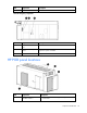
Control and power panels HP POD power panel exterior Item Component Description 1 400A circuit breaker and TVSS system Main input circuit breaker for the A system 2 400A circuit breaker and TVSS system Main input circuit breaker for the B system 3 Cable input A Electrical input feeds for the two 400A supply lines 4 Cable input B Electrical input feeds for the two 400A supply lines Control and power panels 19
HP POD transformers and circuit breakers Item Component Description 1 House panel circuit breaker House panel A bus circuit breaker 2 100A house panel feeder breaker House panel A feeder circuit breaker 3 Busway feeder breaker 225A electrical panel board for electrical busway A 4 House panel circuit breaker House panel B bus circuit breaker 5 100A house panel feeder breaker House panel B feeder circuit breaker 6 Busway feeder breaker 225A electrical panel board for electrical busway B
Swing door components Item Component Description 1 ASSD smoke detection system Contains controls and indicators for the smoke detection system 2 Security transformer * Generates the control voltage for the security system 3 Fire suppression disconnect switch * Fire suppression system disconnection switch and indicator 4 Fire suppression selector switch * Fire suppression selector key switch to select the fire suppression canister 5 Fire alarm control panel Contains controls and indicators
Item Component Description 1 ASSD smoke detection system Contains controls and indicators for the smoke detection system 2 EPO relays Contains controls for the EPO function 3 Transducer and circuit breakers Contains signal transducers and protection circuit breakers 4 ECS system ECS controller for the fan speed controller and indicator 5 Power monitoring 6 Current transducers 7 Redundant fan relays Redundant fan relays 8 Fan speed relays Speed control relays for the fan control 9 B
Cooling system HP POD cooling system CAUTION: Contaminated supply water might cause decreased cooling capacity or disruption in service. The supply water must meet the guidelines states in the HP Performance-Optimized Datacenter Site Requirements Information document. Damage caused by contaminated supply water is not covered by the warranty. The HP POD has six heat exchangers that maintain temperature and cool the equipment installed in the HP POD.
2. Pull the overhead down. Condensation management CAUTION: During operation, avoid leaving the HP POD doors open, to maintain accurate environmental conditions inside the HP POD. Supply cooling water that is above the dew point inside the HP POD to prevent condensation forming on the heat exchangers. The heat exchanger drip tray collects any condensation that forms on the heat exchangers. This collected condensate drains out of the HP POD through the heat exchanger condensate drains.
Water from natural condensation might form. Condensation from the heat exchangers flows to the condensate drain on the rear of the HP POD. The three water main drains, located on the front of the HP POD collect any water from a water main leak. A fifth drain, located on the optional humidifier, removes excess water from the humidifier.
Water quality requirements Water quality requirements and specifications • Closed-loop water must not contain any lime scale deposits or loose debris. • The water must have a low level of hardness, particularly a low level of carbon hardness. Additionally, the water must not be so soft that it attacks the materials with which it comes into contact. • The chilled water temperature to be supplied to the HP POD is 13ºC to 24ºC (55ºF to 75ºF). Freezing water might cause a blockage and damage to the unit.
Frost damage To avoid frost damage, the water temperature must not be allowed to fall below the minimum permissible temperature of +4 ºC (+39.2 ºF) at any point in the water cycle. The water cycle must be drained completely using compressed air before storage or transportation at freezing temperatures or below.
Power management HP POD power The electrical busway is a modular, overhead electrical distribution system that supplies power to the HP POD IT loads. The HP POD can be configured for either non-redundant power or redundant power. In the HP POD there are two electrical busways. • Non-redundant power installation—Both busways are powered from the same power source.
The internal electrical busways provide a location to connect each of the dropboxes, which then power the PDUs. The dropboxes should be staggered on the electrical busways; one connected to the A-side busway and the next connected to the B-side busway. Disabling power • To disable power to a single PDU, open the drop box breaker feeding that PDU and disconnect the PDU from the drop box.
Feature Specification Frequency 50—60 Hz Amps (per busway) 225A Neutral ampacity (per breaker) 225A Amps derated percentage 10% Max usable amps (per busway) 202A Voltage (per busway) 380-415V Grounding Aluminum casing Busway conductors 3 phases + neutral NA standard density HP POD capacities Feature Capacity Tier 1 configuration 450 kW N + N configuration 291 kW 3 phase PDU capacity 17.
Configuration Number of 3phase PDUs per HP POD Number of dropboxes per HP POD Maximum power capacity per rack Total HP POD power capacity Redundant Rack power Power is provided to each rack by PDUs and drop boxes. The PDUs are powered by the drop boxes attached to each electrical busway. For more information regarding power shortages to the PDUs or electrical busway drop boxes, see Troubleshooting (on page 46).
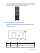
Environmental control system Using the ECS HP recommends connecting the HP POD to your facility BMS, communicating through Ethernet cable connected to the external communications box. For more information, see Configuring the ECS (on page 32). The standard ECS protocol, Modbus TCP/IP, is a data communication protocol for building automation and control networks.
2. The ECS controls can be accessed from a laptop if necessary. To access the ECS using a laptop at the HP POD, connect an Ethernet cable with RJ-45 connectors on both ends between a laptop and the ECS jack on the interior of the HP POD. 3. Complete the following steps to configure your computer so that the network group matches the ECS controller: a. Go to Start>Control Panel>Network Connections. b. Select the Local Area Connection.
c. Click Internet Protocol (TCP/IP).
d. Select Use the following IP address. e. Enter the new IP address. Be sure to specify an IP address in the same network group as the ECS controller. By default the ECS controller uses 192.168.20.1. Your PC can include any number in the group from 2 to 254. 4. Click OK to save and close. Logging in to the ECS 1. Open the CERHOST application.
2. Click File>Connect. 3. Enter the ECS controller IP address and then click OK. ECS overview The main page provides an overview of all HP POD telemetry data This page also shows the active fan step in each zone within the HP POD.
When the status button is red, you must acknowledge active alarms. To enter a password, select ENTER PASSWORD. The default password is CUSTOMER. After entering the password, you can configure basic settings and confirm your password settings. For more information on basic system configuration, see Basic System Configuration (on page 38). NOTE: HP will provide your login username and password. Alarm status overview The Alarm Status Overview provides information about HP POD threshold limitations.
Status indicator Meaning Green The HP POD component is operating in good condition. Red The HP POD component is operating outside normal thresholds. Reset Active alarms are pending. • Clears the alarms and changes the status indicator to green if the condition is good. • Does not clear the alarms, but displays alerts for alarm conditions. The status indicator remains red until the alarm condition is resolved.
Advanced system configuration Item Description Fan current setpoints Indicates fan current set points and enables you to adjust values for fan monitoring Calibrate flowmeter Enables flow rate calibration based on the value of a calibrated flow meter Calibrate chilled water sensor Is accessible only when the flow rate is zero and the chilled water pressure on chilled water supply and return lines is less than 12.75 psi. (1.
Controller Settings Item Description Control routine interval Sets the interval within seconds when the control routine is activated Controller hysteresis The controller has an actuating variable from 0 to 1000 and the fan levels are switched on the following values: • • • • • Step 0–0 to 10 Step 1–10 to 250 Step 2–250 to 500 Step 3–500 to 750 Step 4–750 to 1000 When the actuating value is decreasing, the hysteresis is considered.
Alarm Meaning Solution Leak detection The drain tray senses water. Inspect drain trays to determine if water is from normally occurring condensation. If leak is not from normally occurring condensation, then perform the following steps: 1 Turn off all IT components, so that the components do not overheat. 2 Turn off the water flowing into your HP POD at the facility line. 3 If you are still within your service contract, contact HP service.
Fire alarm sequence of operations If a fire alarm or manual pull station is activated, the HP POD follows this sequence of operations. 1. The HP POD sends an alarm signal to the building fire and security dispatch. 2. The HP POD security lights flash and the horns sound the 30-second evacuation alarm. 3. After a 30-second delay, the HP POD releases the suppressant gas, if the optional fire suppressant system is installed.
Optional components Additional insulation You can choose to have additional insulation added to the walls, ceiling, and floor of your HP POD before shipment. The additional insulation allows you to lower your operating temperature in climates prone to freezing. You must follow cold weather start-up procedures while operating in environments below 50ºF (10ºC) ambient temperatures. Air filter sensor The air filter sensor is an optional component that, if installed, alerts you to change your air filters.
Frequently asked questions HP POD frequently asked questions Question Answer Can I keep the HP POD on the trailer? Yes, if you choose to lease the trailer from HP or if you purchase your own trailer and have the HP POD installed on your trailer prior to shipment. You must also: • Ensure that the site is stable and has been prepared correctly for the additional weight of the trailer. • • Ensure that the site is, and will remain, level. Provide a work platform to access exterior panels.
Question Answer maintain server health, until the root problem can be solved. At what smoke level will an alarm be issued? You can set the four different ranges at which the ASSD panel smoke detector issues an alarm. For more information, see the smoke detector manual supplied with the HP POD. Can I switch out my servers and other rackmounted components? The HP POD supports any IT equipment that uses front to rear air flow cooling to maintain thermal integrity.
Troubleshooting HP POD troubleshooting Issue Resolution The water is not flowing, or flowing too slowly. Verify that all applicable valves are open. Inspect the water lines for blockage, unblock, or replace them as necessary. The HP POD is overheating. If the fan is not functioning, check the integrity of the electrical connection to the fan. If the electrical connection seems OK, replace the fan. If the fan is functioning, check for a kink or blockage in the water line to the heat exchanger.
Specifications HP POD specifications Features Specifications Dimensions 6.7 m x 2.4 m x 3.1 m (22 ft x 8 ft x 10 ft) Maximum weight 7,727 kg (17,000 lb) empty or 24,500 kg (49,500 lb) fullyloaded Maximum power/ cooling 290 kW Maximum rack quantity 10 racks Rack Units (RU) per rack 50 RU Rack Units (RU) maximum 500 RU Nominal power/ cooling per rack 29.1 kW—North American and International Nonredundant mode Nominal power/ cooling per rack 14.
Feature Busway endfeed panels House panels Number of panels 2 2 Capacity 225A, 3-phase 125A, three-phase Poles (per panel) 1, three-pole enclosed circuit breaker 30 pole positions Input circuit breaker information Feature Electrical busway breakers House breakers Number of breakers 1 per busway 1 per panel (main) Main breaker size 225A 125A (main) Branch circuit breaker size N/A Up to 30 poles General characteristics • • • • • • • 1-pole or 2-pole • • Thermalmagnetic trip 3-pol
Feature Specification U height 50U Width 546 mm (21.5 in) Depth 1,000 mm (39.4 in) Maximum load weight 1,360.
Maintenance HP POD and component maintenance schedule Component to be inspected Frequency Electrical connections and wiring—Visual Every 30 days Electrical connections and wiring—Thermal scans Every 180 days Air filter replacement (HP offers an air media kit, part number AT979A) Every 30 days (* or as required) Condensation and water main drainage system (leaks)—Visual Every 30 days Condensation and water main drainage system (leaks)—Functional Every 90 days Busway interconnects (tightened) Eve
CAUTION: Perform this maintenance only if power has been disconnected to the HP POD or the busway breakers are in the open position. Water system maintenance You must maintain your water system quality. Consult a water treatment specialist to perform the following maintenance: Flush the HP POD How often you must flush the HP POD depends on how often you shutdown the HP POD and the water quality.
Before you contact HP Be sure to have the following information available before you call HP: • Technical support registration number (if applicable) • Product serial number • Product model name and number • Product identification number • Applicable error messages • Add-on boards or hardware • Third-party hardware or software • Operating system type and revision level HP contact information For the name of the nearest HP authorized reseller: • See the Contact HP worldwide (in English) we
Appendix I/O controls points list The points list table is a sample of possible point information. The information included might be different for your site and customized HP POD. The following table is an example. For an accurate listing of point information, see your operator and maintenance documentation.
NCE BI IN-11 CoilPan WD1-A Coil Pan Water Detector Alarm NCE25xx MS/T P BI IN-11 F301 1-4-BI IN11 NCE BI IN-12 CoilPan WD2-A Coil Pan Water Detector Alarm NCE25xx MS/T P BI IN-12 F301 1-4-BI IN12 NCE BI IN-13 CoilPan WD3-A Coil Pan Water Detector Alarm NCE25xx MS/T P BI IN-13 F301 1-4-BI IN13 NCE BI IN-14 PipeWD1 -A Pipe Water Detector Alarm NCE25xx MS/T P BI IN-14 F301 1-4-BI IN14 NCE BI IN-15 CoilPan WD4-A Coil Pan Water Detector Alarm NCE25xx MS/T P BI IN-15 F30
NCE AO OUT15 ZN4FanO Zone 4 Fan Output NCE25xx MS/T P AO OUT15 F1059 1-4-AO OUT-15 IOM1 UI IN-1 CHW-F Chill Water Flow IOM 4710 SA Bus UI IN-1 F119 4-1-4-UI IN-1 IOM1 UI IN-2 CHWE-T Chilled Water Entering Temperature IOM 4710 SA Bus UI IN-2 F131 4-1-4-UI IN-2 IOM1 UI IN-3 CHWL-T Chilled Water Leaving Temperature IOM 4710 SA Bus UI IN-3 F131 4-1-4-UI IN-3 IOM1 UI IN-4 FanBank 1-I Fan Bank 1 Current IOM 4710 SA Bus UI IN-4 M12 4-1-4-UI IN-4 IOM1 UI IN-5 FanBank 1
4-I Current Bus IN-3 IOM2 UI IN-4 FanBank 6-I Fan Bank 6 Current IOM 4710 SA Bus UI IN-4 F106 4-1-5-UI IN-4 IOM2 UI IN-5 FanBank 7-I Fan Bank 7 Current IOM 4710 SA Bus UI IN-5 F106 4-1-5-UI IN-5 IOM2 UI IN-6 FanBank 8-I Fan Bank 8 Current IOM 4710 SA Bus UI IN-6 F106 4-1-5-UI IN-6 IOM2 BI IN-7 House Power House Power Status IOM 4710 SA Bus BI IN-7 Unused 4-1-5-BI IN-7 IOM2 BI IN-8 Land Power Land Power Status IOM 4710 SA Bus BI IN-8 Unused 4-1-5-BI IN-8 IOM2
IOM3 BO OUT1 Unused Unused IOM 4710 SA Bus BO OUT-1 Unused 4-1-6-BO OUT-1 IOM3 BO OUT2 Unused Unused IOM 4710 SA Bus BO OUT-2 Unused 4-1-6-BO OUT-2 IOM3 BO OUT3 Unused Unused IOM 4710 SA Bus BO OUT-3 Unused 4-1-6-BO OUT-3 IOM3 CO OUT4 Unused Unused IOM 4710 SA Bus CO OUT-4 Unused 4-1-6-CO OUT-4 IOM3 CO OUT5 Unused Unused IOM 4710 SA Bus CO OUT-5 Unused 4-1-6-CO OUT-5 IOM3 CO OUT6 Unused Unused IOM 4710 SA Bus CO OUT-6 Unused 4-1-6-CO OUT-6 IOM3 CO OUT7
IOM4 CO OUT6 Unused Unused IOM 4710 SA Bus CO OUT-6 Unused 4-1-7-CO OUT-6 IOM4 CO OUT7 Unused Unused IOM 4710 SA Bus CO OUT-7 Unused 4-1-7-CO OUT-7 IOM4 AO OUT8 Unused Unused IOM 4710 SA Bus AO OUT-8 Unused 4-1-7-AO OUT-8 IOM4 AO OUT9 Unused Unused IOM 4710 SA Bus AO OUT-9 Unused 4-1-7-AO OUT-9 IOM5 UI IN-1 ZN5-DP Zone 5 Differential Pressure IOM 4710 SA Bus UI IN-1 F106 4-1-8-UI IN-1 IOM5 UI IN-2 ZN6-DP Zone 6 Differential Pressure IOM 4710 SA Bus UI IN-2
IOM6 UI IN-1 FILT6-DP Filter Differential Pressure IOM 4710 SA Bus UI IN-1 F106 4-1-9-UI IN-1 IOM6 UI IN-2 FILT2-DP Filter Differential Pressure IOM 4710 SA Bus UI IN-2 F106 4-1-9-UI IN-2 IOM6 UI IN-3 FILT4-DP Filter Differential Pressure IOM 4710 SA Bus UI IN-3 F106 4-1-9-UI IN-3 IOM6 UI IN-4 FILT1-DP Filter Differential Pressure IOM 4710 SA Bus UI IN-4 F106 4-1-9-UI IN-4 IOM6 UI IN-5 FILT5-DP Filter Differential Pressure IOM 4710 SA Bus UI IN-5 F106 4-1-9-UI IN-
Regulatory compliance notices Regulatory compliance identification numbers For the purpose of regulatory compliance certifications and identification, this product has been assigned a unique regulatory model number. The regulatory model number can be found on the product nameplate label, along with all required approval markings and information. When requesting compliance information for this product, always refer to this regulatory model number.
• Low Voltage Directive 2006/95/EC • EMC Directive 2004/108/EC • Ecodesign Directive/2009/125/EC, where applicable • Machinery Directive 98/37/EEC CE compliance of this product is valid if powered with the correct CE-Marked AC adapter provided by HP.
BSMI notice Chinese notice Class A equipment Korean class A notice Japanese class A notice Regulatory compliance notices 62
Acronyms and abbreviations AHJ Authority Having Jurisdiction ASHRAE American Society of Heating, Refrigerating and Air-Conditioning Engineers ASSD air sampling smoke detector BPMS branch power monitor system ECS environmental control system EPMS electrical power monitor system EPO emergency power off FAQ frequently asked questions FC fan control HEX heat exchanger ISO International Organization for Standardization NEMA National Electrical Manufacturers Association Acronyms and abbreviations 63
PDU power distribution unit POD Performance-Optimized Datacenter TVSS Transient Voltage Surge Suppression Acronyms and abbreviations 64
Index A D acceptable water quality specifications 26 access 43 advanced system configuration 39 air and water heat exchanger maintenance 51 air filter replacement 51 air filter sensor 43 alarm status overview 37 alarms, ECS 40 alarms, safety and security 41 authorized reseller 52 downloading files 52 drains 24, 51 B basic system configuration 38 before you begin 6 before you contact HP 52 BSMI notice 62 C cables, FCC compliance 60 Canadian notices 60 Chinese notice 62 cold weather protection 43 cold we
installation 12, 13 installing the POD at your facility 13 insulation 43 J Japanese notice 62 K Korean notices 62 L leak detection 25 LEDs, troubleshooting 44, 46 leveling requirements 26 logging in to ECS 35 M maintenance 50, 51 maintenance schedule 50 maintenance, electrical busway 50 maintenance, water system 51 managing ECS settings 32 modifications, FCC notice 60 O operator safety 6 optional components 43 regulatory compliance notices 60, 61 required information 52 required tools 13 requirements,