HP Performance-Optimized Datacenter, 12 m (40 ft) User Guide Part Number 573766-002 June 2010 (Second Edition)
© Copyright 2010 Hewlett-Packard Development Company, L.P. The information contained herein is subject to change without notice. The only warranties for HP products and services are set forth in the express warranty statements accompanying such products and services. Nothing herein should be construed as constituting an additional warranty. HP shall not be liable for technical or editorial errors or omissions contained herein. Confidential computer software.
Contents Site preparation and safety considerations ...................................................................................... 6 Before you begin.......................................................................................................................................... 6 Safety information ........................................................................................................................................ 6 Operator safety.........................................
Fan control panel ............................................................................................................................. 33 Fire alarm control panel .................................................................................................................... 33 House panels ................................................................................................................................... 33 House relay transfer panel .............................................
Canadian notice ........................................................................................................................................ 51 European Union regulatory notice ................................................................................................................ 51 Disposal of waste equipment by users in private households in the European Union .......................................... 52 BSMI notice ....................................................................
Site preparation and safety considerations Before you begin For more information on site requirements, specifications, water quality requirements, power management requirements, and supported facility connections, see the HP Performance-Optimized Datacenter Site Requirements documentation. The location of various components or subsystems in your HP POD might vary from this documentation. For final placement specifications, see your operations and maintenance manual.
CAUTION: All customer supplied water fittings must be composed of carbon steel, stainless steel, or copper. Do not use cast iron, aluminum, or PVC fittings. CAUTION: During operation, avoid leaving the HP POD doors open, to maintain accurate environmental conditions inside the HP POD. CAUTION: If the HP POD is located outdoors, do not work in the hot aisle during inclement weather. If the chilled water stops flowing into the HP POD: 1. Turn off IT equipment. 2.
Component identification HP POD components HP POD external components Item Component Description 1 Drain lines Collect water from the drain pans and removes it from the HP POD 2 Electrical busway end feeds Main source of distributing power throughout the HP POD 3 Heat exchangers Use chilled water to cool the air 4 Rear service doors Enable access to the rear of the rack-mounted components 5 Entrance doors Enable access to the front of the rack-mounted components 6 Fan units Circulate th
If any of the racks within the HP POD contain empty U space, then to avoid compromising the integrity of the hold and cold aisle temperatures, you must use the HP POD Filler Panel. Filler panels are available from HP in 10-pack quantities (AQ682A) and 100-pack quantities (AS993A).
Internal emergency components Item Component Description 1 Internal fire strobe and horn Indication of a fire alarm condition within the HP POD 2 EPO buttons Stop power to the HP POD and activates the EPO strobe 3 EPO strobe Activated when an EPO button is pressed 4 Fire alarm manual pull stations Activate the fire strobes and horns Component identification 10
Installation HP POD shipping contents Standard density 40-ft HP POD Component Quantity Part number HP 50U rack 22 AT978A Side panel 50U kit 1 AN991A 50U rack bracket kit 21 AP014A Rack interface seal kit 21 AP013A 11 (non-redundant) AS613A (NA) 22 (redundant) AS633A (International) 3-phase HP POD PDU bracket kit 44 AQ683A PDU 22 (non-redundant) AS614A (NA) 44 (redundant) AS634A (International) Component Quantity Part number HP 50U rack 22 AT978A Side panel 50U kit 1 AN991A
NOTE: To provide power to your HP POD, you can either: • • Purchase an HP Transformer and HP Switchboard and engineer your site power to support their requirements o Non-redundant power—one of each o Redundant power—two of each Engineer your own site power o Standard HP POD—1200A minimum o High density HP POD—1600A minimum The HP POD is delivered with heavy duty filler panels installed in every empty U space of the racks.
Installing the HP POD The following steps are an overview of the installation procedure for installing an HP POD. Service professionals must connect your power and water. IMPORTANT: All wiring in and around the HP POD must be completed by a licensed electrician. IMPORTANT: All plumbing to and from the HP POD must be completed by a licensed plumber. Connecting the water CAUTION: All customer supplied water fittings must be composed of carbon steel, stainless steel, or copper.
NOTE: The HP POD pipe design is rated for a maximum pressure rating of 150 psi. 5. Verify that your facility water pressure differential (between supply and return) is within the acceptable range (25 psi maximum). NOTE: For easy reference, the water piping is labeled with green tape and white arrows pointing in the direction of the water flow. 6. (Optional) Connect the HP POD humidifier to the domestic or industrial water drain (1) and supply (2) lines.
1. Verify that the HP POD, transformer, and switchboard are in the final locations. NOTE: The following steps detail the connection procedure for a non-redundant power installation. If you are installing your HP POD for redundant power, you will have connections to two transformers and two switchboards. 2. Make the power connections. a. Connect the main power leads from your facility to the transformer (1 to 2). Each connection is labeled with colored tape, according to local standard requirements. b.
4. Close the required breakers on the switchboard. 5. Close the main breaker in both of the house panels on the exterior of the HP POD. 6. Close the remaining breakers in the house panel, following the panel schedule on the inside of the house panel. NOTE: If you are installing a high density HP POD, you must also close the main breaker in the electrical busway 3 panel. 7. Close the main breakers in the electrical busway panels.
8. Inside the HP POD, close the breaker on each drop box that is connected to a rack of IT components. 9. Power up your remaining racks and IT components, following your standard IT startup procedure. Starting up the HP POD in cold weather IMPORTANT: When the internal HP POD ambient air temperature is below 50°F (10°C), to ensure that the IT is not subjected to air temperatures that are too cold, you must follow incremental procedures. 1. 2.
10. Power up the servers and other IT equipment. Also simultaneously power off any portable heaters, if used. When powering up each server unit, HP recommends that heat be equally distributed across the length of the HP POD. Power on one server unit at a time moving from one rack to the adjacent rack. Do not power on server units in the same rack before moving to the next adjacent rack. NOTE: HP POD space temperature rate of change should not exceed 18°F (10°C) per hour with operating servers. 11.
Cooling system HP POD cooling system CAUTION: Contaminated supply water might cause decreased cooling capacity or disruption in service. The supply water must meet the guidelines states in the HP Performance-Optimized Datacenter Site Requirements Information document. Damage caused by contaminated supply water is not covered by the warranty. The HP POD has 12 heat exchangers that maintain temperature and cool the equipment installed in the HP POD.
2. Pull the overhead down. Condensation management CAUTION: During operation, avoid leaving the HP POD doors open, to maintain accurate environmental conditions inside the HP POD. Supply cooling water that is above the dew point inside the HP POD to prevent condensation forming on the heat exchangers. The heat exchanger drip tray collects any condensation that forms on the heat exchangers. This collected condensate drains out of the HP POD through the heat exchanger condensate drains.
Water from natural condensation might form. Condensation from the heat exchangers flow to the three condensate drains across the rear of the HP POD (1). The water main drain catches any water from a water main leak (2). The humidifier drain removes excess water from the humidifier (3). Item Component 1 Heat exchanger condensate drains 2 Water main supply/return drain 3 Humidifier drain IMPORTANT: You might have to pipe directly to your local storm or sanitary drain, depending on local jurisdiction.
Water quality requirements Water quality requirements and specifications • Closed-loop water must not contain any lime scale deposits or loose debris. • The water must have a low level of hardness, particularly a low level of carbon hardness. Additionally, the water must not be so soft that it attacks the materials with which it comes into contact. • The chilled water temperature to be supplied to the HP POD is 13ºC to 24ºC (55ºF to 75ºF). Freezing water might cause a blockage and damage to the unit.
Water supply specifications Feature Specification Facility input temperature to HP POD 12º to 24ºC (55º to 75ºF) Working pressure 1,034 kPa (150 psi) HP POD pressure drop 1,732 kPa (25 psi) HP POD water flow rate 908.5 l/min (240 gal/min) Cooling water supply and return connections Two 10.
Water temperature The temperature of the water supplied to the HP POD must be 13ºC to 24ºC (55ºF to 75ºF). Freezing water might cause a blockage and damage to the unit. The minimum server inlet temperature is 10°C (50°F).
Power management HP POD power The electrical busway is a modular, overhead electrical distribution system that supplies power to the HP POD IT loads. The HP POD can be configured for either non-redundant power or redundant power. In the standard density HP POD there are four electrical busways. • Non-redundant power installation—All four busways are powered from the same power source.
The internal electrical busways provide a location to connect each of the drop boxes, which then power the PDUs. Stagger the drop boxes on the electrical busways; one connected to the A-side busway and the next connected to the B-side busway. Disabling power • To disable power to a single PDU, open the drop box breaker feeding that PDU and disconnect the PDU from the drop box.
Feature Specification Number of busways 4 Frequency 50-60 Hz Amps (per busway) 225A Neutral ampacity (per breaker) 225A Amps derated percentage 10% Max usable amps (per busway) 202A Voltage (per busway) 380-415V Grounding Aluminum casing Busway conductors 3 phases + neutral NA standard density HP POD capacities Feature Capacity Tier 1 configuration 450 kW N + N configuration 291 kW 3 phase PDU capacity 17.
Feature Specification Amps (per breaker) 225A Neutral ampacity (per breaker) 225A Amps derated percentage 10% Max usable amps (per breaker) 202A Voltage (per busway) 380-415V Grounding Aluminum casing Busway conductors 3 phases + neutral NA high density HP POD capacities Feature Capacity Tier 1 configuration 600 kW N + N configuration 380 kW 3 phase PDU capacity 17.
NA high density HP POD configurations Configuration Number of 3 phase PDUs per HP POD Number of dropboxes per HP POD Power capacity per rack Total HP POD power capacity 6 x 225 44 22 44 kW 600 kW 44 22 17.28 kW 380 kW Non-redundant 6 x 225 Redundant International high density HP POD configurations Configuration Number of 3 phase PDUs per HP POD Number of dropboxes per HP POD Power capacity per rack Total HP POD power capacity 6 x 225 44 22 44 kW 600 kW 44 22 22 kW 436.
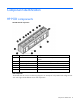
Control panel External control panels Item Component Description 1 Electrical busway enclosed circuit breakers ("Electrical busway enclosed circuit breaker" on page 31) 225A electrical circuit breaker panels that provide overcurrent protection to the electrical busways: • Four electrical circuit breaker panels are installed in the standard HP POD. • Six electrical circuit breaker panels are installed in the high density HP POD.
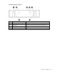
Item Component Description page 31) 12 Fire alarm XFMR Powers 120V Fire Alarm system components, if required 13 Fire alarm control panel (on page 33) Contains controls and status indicators for the fire alarm system 14 EPO panel (on page 31) Contains controls and status indicators for the EPO system *Optional component ("Optional components" on page 39) Smoke detector panel The smoke detector panel contains an aspirating smoke detection system that draws air from the piping network inside the H
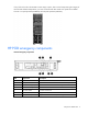
To enable remote access to the EPO system, switch to Bypass mode. Callou t Component Description 1 Power On LED Indicates the EPO is functional, and operating in Test mode, Armed mode, or Bypass mode. 2 EPO Armed mode LED Indicates the EPO is operating in Armed mode. 3 Reset button Resets the EPO system after an EPO alarm has been triggered. 4 Three way key-operated switch Sets the EPO operating mode (Test, Armed, or Bypass).
Armed mode—Pressing a red EPO button on the POD causes the following events: • The red System Alarm/EPO Shutdown light on the EPO panel illuminates to indicate that an EPO switch has been activated. (This light remains illuminated until all EPO buttons are restored to their normal state by means of a key release mechanism, and the Reset button on the EPO panel is pressed.) • The EPO activated relay is energized and sends a signal to the EPO panel to energize the associated control relays.
House relay transfer panel The House relay transfer panel automatically transfers the loads from House panel A to House panel B in the event of a power failure. Redundant relay panel The house relay transfer panel automatically transfers the loads from house panel A to house panel B in the event of a power failure. Security panel location If you decide you want to install a security panel, the HP POD has a predesignated location for a security panel.
Environmental control system Using the ECS The HP POD is designed as a standalone system that does not require any connection or controls from a facility building management system. The HP POD ECS can connect to a site BMS through Ethernet cable, connected to the ECS port located in the hot aisle. The HP POD ECS communicates through BACnet protocol. Connecting the HP POD ECS to a site BMS requires additional engineering, labor and costs.
Logging in to the HP POD ECS 1. Install and configure JAVA JRE 1.6.0_07-b06. You must have this version of Java™. 2. For your laptop to use the Ethernet port, turn on DHCP. 3. Plug the Ethernet cable into the designated ECS jack on the interior of the HP POD. A limited connection warning might appear. 4. Retrieve the HP POD MAC address from the inside of the ECS panel on the exterior of the HP POD. 5. Open Microsoft® Internet Explorer. 6.
8. Log in to Johnson Controls. 9. To view the status points: a. Select the All Items tab on the left side of the page. b. Select the User Views folder. Click the + to expand the folder and see the subcategories. c. Select any subcategory to view its status and description. ECS alarms The alarms pertaining to the health of the HP POD and its components are relayed through the ECS. Alarm Meaning Solution Fan failure One of the fans is not working.
Alarm Meaning Solution 4 If you are not within your service contract, repair the source of the leak. Change filter* The return air filters are full. Replace the return air filters. High temperature The cold aisle temperature has surpassed the set point temperature. Check to make sure that you have water flowing into your HP POD and that the fans are blowing. If you are still within your service contract, contact HP service. Low temperature The cold aisle temperature is too low.
Optional components Cold weather protection The cold weather protection option provides additional insulation that enables HP POD operations in temperatures as low as -20°F (-29°C). You must follow cold weather start-up procedures while operating in environments below 50°F (10°C) ambient temperatures. Air filter sensor The air filter sensor is an optional component that, if installed, alerts you to change your air filters. The sensors are located near each of the eighteen air filters.
The standard cables should allow for placing the transformer and switchboard approximately 3.0 m (10 ft) away from the HP POD. Installation costs assume that connections are within the 3.0 m (10 ft) recommendation. If you place the transformer and switchboard more than 3.0 m (10 ft) away from the HP POD, additional planning and costs are involved.
Frequently asked questions HP POD frequently asked questions Question Answer Can I keep the HP POD on the trailer? Yes, if you choose to lease the trailer from HP or if you purchase your own trailer and have the HP POD installed on your trailer prior to shipment. You must also: • Ensure that the site is stable and has been prepared correctly for the additional weight of the trailer. • Provide a work platform to access exterior panels.
Question Answer HP recommends shutting down all IT components or pressing any EPO button to manually power down the servers, to maintain server health, until the root problem can be solved. At what smoke level will an alarm be issued? You can set the four different ranges at which the ASSD panel smoke detector issues an alarm. For more information, see the smoke detector manual supplied with the HP POD.
Troubleshooting HP POD troubleshooting Issue Resolution The water is not flowing, or flowing too slowly. Verify that all applicable valves are open. Inspect the water lines for blockage, unblock, or replace them as necessary. The HP POD is overheating. If the fan is not functioning, check the integrity of the electrical connection to the fan. If the electrical connection seems OK, replace the fan. If the fan is functioning, check for a kink or blockage in the water line to the heat exchanger.
Specifications Standard density HP POD specifications Features Specifications Dimensions 12 m x 2.4m x 2.7m (40 ft x 8 ft x 9.5 ft) Maximum weight 11,340 kg (25,000 lb) empty- 50,348 kg (111,000 lb) fullyloaded Maximum power/ cooling 450 kW Standard HP POD Maximum rack quantity 22 racks Rack Units (RU) per rack 50 RU Rack Units (RU) total 1100 RU Nominal power/ cooling per rack 20.45 kW – North America & International Nonredundant mode Nominal power/ cooling per rack 13.
Features Specifications Maximum weight 11,340 kg (25,000 lb) empty- 50,348 kg (111,000 lb) fullyloaded Maximum power/ cooling 600 kW Standard HP POD Maximum rack quantity 22 racks Rack Units (RU) per rack 50 RU Rack Units (RU) total 1100 RU Nominal power/ cooling per rack 27.27 kW – North America & International Nonredundant mode Nominal power/ cooling per rack 17.28 kW – North America Redundant mode 19.84 kW – International Maximum power/ cooling per rack 34.
Feature Electrical busway breakers House breakers Number of breakers 1 per busway 1 per panel (main) Main breaker size 225A 125A (main) Branch circuit breaker size N/A Up to 30 poles General characteristics • • • • • • • 1-pole or 2-pole • • thermalmagnetic trip 3-pole 100% rated thermalmagnetic trip 25 kA interrupt capacity provide with shunt trip coil sized per panel schedule 14 kA interrupt capacity Fire alarm panel connections The electrical layout of the fire alarm system is as desc
Thermal and air flow performance Maximum thermal and air flow performance parameters HP POD specification Air temperature—Inlet to rackmounted components Hot aisle setpoint temperature in ECS Chilled water temperature 12°–24°C (55°–75°F) Total rack-mounted component air flow Variable as required to maintain hot aisle setpoint temperature Heat rejection capacity 600 kW Environmental specifications Feature Specification Operating temperature -18ºC to 54ºC (0ºF to 130ºF).
Maintenance HP POD and component maintenance schedule Component to be inspected Frequency Electrical connections and wiring—Visual Every 30 days Electrical connections and wiring—Thermal scans Every 180 days Air filter replacement (HP offers an air media kit, part number AT979A) Every 30 days (* or as required) Condensation and water main drainage system (leaks)—Visual Every 30 days Condensation and water main drainage system (leaks)—Functional Every 90 days Busway interconnects (tightened) Eve
CAUTION: Perform this maintenance only if power has been disconnected to the HP POD or the busway breakers are in the open position. Water system maintenance You must maintain your water system quality. Consult a water treatment specialist to perform the following maintenance: Flush the HP POD How often you must flush the HP POD depends on how often you shutdown the HP POD and the water quality.
Before you contact HP Be sure to have the following information available before you call HP: • Technical support registration number (if applicable) • Product serial number • Product model name and number • Product identification number • Applicable error messages • Add-on boards or hardware • Third-party hardware or software • Operating system type and revision level HP contact information For the name of the nearest HP authorized reseller: • See the Contact HP worldwide (in English) we
Regulatory compliance notices Regulatory compliance identification numbers For the purpose of regulatory compliance certifications and identification, this product has been assigned a unique regulatory model number. The regulatory model number can be found on the product nameplate label, along with all required approval markings and information. When requesting compliance information for this product, always refer to this regulatory model number.
• Low Voltage Directive 2006/95/EC • EMC Directive 2004/108/EC • Ecodesign Directive/2009/125/EC, where applicable • Machinery Directive 98/37/EEC CE compliance of this product is valid if powered with the correct CE-Marked AC adapter provided by HP.
BSMI notice Chinese notice Class A equipment Korean class A notice Japanese class A notice Regulatory compliance notices 53
Acronyms and abbreviations AHJ Authority Having Jurisdiction ASHRAE American Society of Heating, Refrigerating and Air-Conditioning Engineers ASSD air sampling smoke detector BPMS branch power monitor system ECS environmental control system EPMS electrical power monitor system EPO emergency power off FAQ frequently asked questions FC fan control HEX heat exchanger ISO International Organization for Standardization NA North American Acronyms and abbreviations 54
NEMA National Electrical Manufacturers Association PDU power distribution unit POD Performance-Optimized Datacenter TVSS Transient Voltage Surge Suppression Acronyms and abbreviations 55
Index A acceptable water quality specifications 22 access 39 air and water heat exchanger maintenance 49 air filter replacement 49 air filter sensor 39 alarms, ECS 37 B before you begin 6 before you contact HP 50 BSMI notice 53 C cables, FCC compliance 51 Canadian notices 51 Chinese notice 53 cold weather protection 39 cold weather startup 17 commissioning the POD 18 component health 6 components 8 components, identification 8 connecting the power 14 connecting the water 13 contact information 50 contents
M maintenance 48, 49 maintenance schedule 48 maintenance, water system 49 managing ECS settings 35 modifications, FCC notice 51 O operator safety 6 optional components 39 P periodic maintenance 48 plumbing materials 23 power connections 14 power distribution kit 26, 28 power distribution unit (PDU) 28, 29 power distribution, Starline 25, 26 power management 25 power, rack 29 precautions, water 23 preinstallation checklist 12 thermal air flow performance 47 third-party components 49 transformer and switch