HP Performance Optimized Datacenter 240e North America (Adiabatic) Maintenance and Service Guide Abstract This guide is intended for the person who operates and maintains HP POD 240e NA.
© Copyright 2013 Hewlett-Packard Development Company, L.P. The information contained herein is subject to change without notice. The only warranties for HP products and services are set forth in the express warranty statements accompanying such products and services. Nothing herein should be construed as constituting an additional warranty. HP shall not be liable for technical or editorial errors or omissions contained herein.
Contents Illustrated parts catalog ................................................................................................................. 5 Structural component identification ................................................................................................................. 5 Life safety component identification ................................................................................................................ 6 Electrical power component identification ...............
Qualified personnel .......................................................................................................................... 41 Adiabatic ........................................................................................................................................ 41 ECS ................................................................................................................................................ 43 Electrical .....................................................
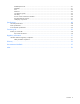
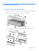
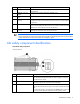
Illustrated parts catalog Structural component identification The HP POD 240e NA documentation frequently refers to these specific components of the HP POD 240e NA. The following figure shows the assembled HP POD 240e NA structural components. The following figure shows the exploded view of the individual sections of the HP POD 240e NA.
Item Component Description 1 Canopy The canopy has two 6.10 m (20 ft) parts that are installed on top of the HP POD 240e NA. 2 Adiabatic units and cradles AHU service area end walls IT section A (primary structure) Each of the four cradles contain three Adiabatic units. 5 Hot aisle The hot aisle structure is a separate space where hot exhaust air from the servers can be expelled out of the structure or recirculated. The HP POD 240e isolates the IT sections from the hot aisle for efficiency.
Exit sign locations Top view shown Internal emergency lighting Top view shown Internal emergency status indicators Illustrated parts catalog 7
Top view shown There is one fire strobe light in each aisle of the HP POD 240e NA. When illuminated, these lights indicate a fire alarm condition within the HP POD 240e NA. External emergency status indicators Item Component Description 1 External EPO status indicator Indication of operating status: • • • 2 Fire strobe light White—Normal operating mode Yellow—Bypass operating mode Red—EPO shutdown mode Indicates a fire alarm condition within the HP POD 240e NA.
Electrical power component identification WARNING: To avoid the risk of personal injury or loss of life, all personnel must comply with PPE requirements when opening or working inside areas of the HP POD 240e NA that are marked as hazardous voltage, per NFPA 70E in accordance with NEC (NA) and IEC (EMEA and APJ).
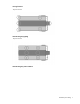
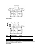
End view shown External safety labels End view shown Callout Electrical safety label Description 1 Danger sign Reminds you that the electrical panels must only be accessed by authorized personnel. 2 Disconnect label Provides the disconnect order for all of the electrical panels. 3 Caution Cautions you about isolating power from the product. 4 Arc flash warning Reminds you of arc flash danger and required PPE.
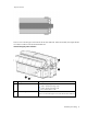
End view shown Callout Electrical safety label Description 1 Input power Lists the input power information 2 Panel schedule/circuit breaker table Lists the layout and designation for all circuit breakers on the panel 3 Fuse type table Lists all fuse types and sizes 4 Wire color code 415/240V wye color codes • • • • • Purple/Brown Purple/Orange Purple/Yellow Purple/White—Neutral Green and yellow—Equipment ground Electrical power disconnect map label location Illustrated parts catalog 11
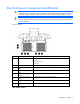
Control cabinet component identification All circuits in the control cabinet are labeled with the panel name and circuit breaker number. Each IT section has one control cabinet that houses the various control components for that IT section. IT section A control cabinet The ECS and fire panel controls are located in the IT section A control cabinet.
Item Component Description NA PLC* The computer located on the inside door of the control cabinet that controls the ECS system *These components are only installed in the IT section A control cabinet.
For more information about racks and network cabling, see the HP POD 240e NA Networking Guide. Replaceable components Each HP POD 240e NA is unique and the specific replaceable components vary for each POD. For specific replaceable component information, see the Operations and Maintenance Manual for the HP Performance Optimized Datacenter 240e North America (Adiabatic).
AHU system AHU operator safety WARNING: Turn off power to the unit unless you are performing tests that require power. With power and controls energized, the unit could begin operating automatically at any time. To prevent personal injury, stay clear of rotating components as automatic controls might start them unexpectedly.
Removal and replacement procedures Safety considerations The HP POD 240e NA is Listed to UL 69050 Part 1 and Part 22 as an Information Technology Product and Classified in accordance with the National Electric Code NFPA 70. The HP POD 240e NA is not habitable or suitable for human occupancy. The HP POD 240e NA has service access areas for periodic maintenance and service.
Removing the Adiabatic media 1. Remove the 10mm screws securing the access panel that is located to the left of the electrical controls panel (1), and then remove the access panel (2). 2. Remove the water supply drip header assembly by lifting it off of the Adiabatic media.
3. Remove the screws securing the Adiabatic media bracket (1), and then lift up and remove the bracket (2). 4. Remove the Adiabatic media by lifting it straight up and out.
Replacing the Adiabatic media 1. Insert the new Adiabatic media into the metal frame. Be sure that the directional airflow arrows on the Adiabatic media are correct. 2. Replace the Adiabatic media bracket and screws. 3. Replace the water supply drip header assembly. 4. Replace the Adiabatic media access panel. Air filter box The Adiabatic unit comes with four air filters and two pre-filters installed. The air filter sensor indicates when a filter must be changed through the ECS.
Removing the air filter 1. Locate the filter box on the rear of the AHU. 2. Remove the 10mm screws that secure the access panel on the bottom of the filter box (1), and then remove the filter access panel (2).
3. Move the filter latch to the side (1), and then remove the two filters, one filter at a time (2). 4. Repeat step 3 to remove the other two filters, and then remove the pre-filters from the metal frame.
Replacing the air filter 1. Insert the new pre-filter into the metal frame. Be sure that the directional airflow arrows on the pre-filter are correct. 2. Insert the new air filters. Be sure that the directional airflow arrows on the filter are correct (1). 3. Close the filter latch (2) by moving it to the side, and then replace the filter access panel. Busway drop box The internal electrical busways provide a location to connect each of the drop boxes, which then power the PDUs.
Removing the busway drop box 1. Turn the power off by opening both breakers on the busway drop box (1). 2. Disconnect the PDUs that are connected to the busway drop box (2). 3. Use a socket wrench to loosen and remove the bolt securing the busway drop box to the retaining hardware bracket (1). 4. Slide the hardware bracket to the right along the busway, completely disconnecting it from the busway drop box (2). WARNING: Use caution when removing and replacing the busway drop box.
5. Rotate the busway drop box 90° so that it is perpendicular to the electrical busway, and then remove the drop box from the electrical busway (3). Replacing the busway drop box WARNING: Use caution when removing and replacing the busway drop box. The drop box weighs approximately 9 kg (20 lb). 1. Place the silver drop box bracket on the electrical busway where you want to replace the busway drop box (1). 2.
4. Secure the busway drop box to the retaining hardware bracket by using a socket wrench to insert and tighten a bolt (4). 5. Connect the PDUs to the busway drop box (1). 6. Turn the power on by closing both breakers on the busway drop box (2).
DIN rail components The HP POD 240e NA contains several types of electrical components that are attached using DIN rails. The methods to remove and replace the DIN rail components differ depending on the type of components and the manufacturer of the components.
3. Grasp the pull tab to disengage the control relay module from the DIN rail (1) and remove the control relay module (2). Replacing the control relay module 1. Align the control relay module with the mounting and power connections. 2. Slide the module until it clicks into the DIN rail. 3. Reconnect all wiring to the control relay module. Door position devices Magnetic contacts Magnetic contacts are located on all doors and cabinets.
You need a screwdriver and scissors for installation. Removing the magnetic contacts 1. Remove the two screws that secure the upper magnet (1). 2. Cut the tie wrap (2), and then loosen the nut on the POD structure that secures the wire. 3. Pull the wire all the way through to the point of entry or ECS panel (3). Replacing the magnetic contacts 1. Feed the wire all the way through from the point of entry or ECS panel (1). 2.
EPO button There is one EPO button by each door of the HP POD 240e NA, for a total of six EPO buttons. You need a screwdriver for installation. Removing the EPO button 1. Remove the three screws securing the tamper cover (1), and then remove the tamper cover (2).
2. Remove the four screws securing the EPO button (1), and then remove the EPO button (2). Replacing the EPO button 1. Replace the EPO button (1), and then replace the four screws that secure the EPO button (2).
2. Replace the tamper cover (1), and then replace the three screws that secure the tamper cover (2). Exhaust fan damper Each Adiabatic unit contains 10 exhaust fan dampers. You need a screwdriver for installation. Removing the exhaust fan damper 1. Remove the 10mm bolts that secure the exhaust fan damper guard to the exhaust fan damper (1), and then remove the exhaust fan damper guard (2). 2.
3. Remove the 10mm bolt that secures the actuator assembly to the exhaust fan damper (2), and then remove the actuator assembly (3). 4. Remove the 10mm bolts securing the exhaust fan damper to the exhaust fan (1), and then remove the exhaust fan (2). Replacing the exhaust fan damper 1. Insert the new exhaust fan damper onto the metal frame, and then secure the exhaust fan damper with the 10mm screws. 2. Replace the actuator assembly. 3. Replace the exhaust fan damper guard.
Humidity and temperature sensor The HP POD 240e NA contains four humidity and temperature sensors, which are located throughout the IT sections. You need a screwdriver for installation. Removing the humidity and temperature sensors 1. Remove the four screws that secure the sensor cover (1), and then remove the cover (2).
2. Loosen the sensor wires by turning the nut counter clockwise (1), remove the sensor wires from the terminal block, and then remove the sensor wires (3). 3. Remove the two screws that secure the sensor (1), and then remove the sensor (2).
Replacing the humidity and temperature sensors 1. Replace the sensor (1), and then secure the sensor with two screws (2). 2. Insert the sensor wire into the nut (1), secure the wire by turning the nut clockwise (2), and then insert the wire into the terminal block (3).
3. Replace the sensor cover (1), and then secure the cover with four screws (2). Lights The HP POD 240e NA contains LED lighting in the hot aisle and in both of the IT sections. It also includes fluorescent lights in the service area.
Top view shown Removing the LED light You need a screwdriver for installation. 1. Disconnect power from the LED light. 2. Remove the screws (1). 3. Remove the LED light assembly (2). Replacing the LED light 1. Place the LED light where you want to secure it (1). 2. Insert the screws (2).
3. Reconnect power to the LED light. Removing the fluorescent light 1. Remove the fluorescent light cover (1), if installed. 2. Rotate the bulb (2), and then pull it straight out (3). Replacing the fluorescent light 1. Seat the fluorescent bulb (1). 2. Rotate the bulb, and then snap it into place (2).
3. Close the cover (3). VESDA filter The VESDA filter sensor notifies you through the ECS when a filter must be changed. HP recommends that you periodically inspect and change each VESDA filter. A VESDA filter can be replaced during normal HP POD 240e NA operation. You need a screwdriver for installation. Removing the VESDA filter 1. Remove the filter cover on the front of the VESDA unit.
2. Remove the 10mm screw that secures the VESDA filter (1), and then remove the filter (2). Replacing the VESDA filter 1. Insert the new VESDA filter (1), and then replace the 10mm screw that secures the filter (2). 2. Replace the VESDA filter cover.
Maintenance Periodic maintenance Perform periodic inspections to be sure the HP POD 240e NA continues to perform to design parameters. During period inspections, observe the following guidelines on electrical connections and wiring.
Component to be inspected Task Frequency Capable party — Verify that fan operation can be ramped up to 100% and back down to the desired setpoint. Record the evaporator fan amperage draw. Semi-annually Qualified personnel Quarterly Qualified personnel Inspect the unit for: Quarterly Qualified personnel — Adiabatic unit dampers, actuators, and rods • • • Heaters — Adiabatic media drip pan drain lines and p-trap Clean as necessary.
Component to be inspected Task Frequency Capable party Spray head Inspect spray heads for blockage. Clean as necessary. Inspect water supply to be sure water is at a potable standard. When necessary, follow winterization procedures to ready the Adiabatic system for winter temperatures. Restore the Adiabatic system to operation by reversing the necessary portions of the winterization procedure.
Component to be inspected Task Frequency Capable party — POD shutdown required Conduct torque checks on the following: Annually Licensed electrician Every 2 years Licensed electrician Every 2 years Licensed electrician Every 2 years Licensed electrician Every 2 years Licensed electrician Every 2 years Licensed electrician Quarterly Licensed electrician/ Qualified personnel Annually Licensed electrician Quarterly Licensed electrician/ Qualified personnel Every 3 years 3rd party Testi
Component to be inspected Sensors Task Frequency Capable party Verify proper operation of: Annually Qualified personnel • • — Lighting Internal POD temperature sensors (thermometer) Relative humidity sensors (RH meter) Investigate discrepancies and troubleshoot. Replace as necessary. POD shut down required Annually Qualified personnel Calibrate (zero out) POD differential sensors. Investigate discrepancies and troubleshoot. Replace as necessary.
Life safety Component to be inspected Task Manual EPO shunt trip EPO functional test Annually Manually initiate EPO shutdowns with the six internal and external push buttons (if installed) in succession. Verify that all shunt-trips on all panels trip. EPO functional test Annually Initiate a thermal (automatic) EPO shutdown via EPO temperature switches that are located in the hot aisle. Verify that all shunt-trips on all panels trip.
Component to be inspected Task Frequency — Visually inspect and test the Annually operation of the door access card readers, electric strikes, and door release switches at each personnel door and in each personnel door panic bar. Capable party Qualified personnel HP POD 240e NA structure Component to be inspected Task Frequency Capable party Complete structure Visually inspect the structural integrity.
Specifications General specifications Features Specifications Overall dimensions • • • Height—6.74 m (22 ft 1 1/4 inches) Length—13.77 m (45 ft 2 1/4 inches) including hot aisle porch Width—9.
Environmental specifications Feature Specification Operating temperature -28ºC to 54ºC (-20ºF to 130ºF) Non-operating temperature* -29ºC to 54ºC (-20ºF to 130ºF) Operating humidity 0% to 100% relative non-condensing Non-operating humidity* • • Operating altitude -76.2 to 3,048 m (-250 to 10,000 ft) Non-operating altitude -76.
Contacting HP Before you contact HP Be sure to have the following information available before you call HP: • Active Health System log (HP ProLiant Gen8 or later products) Download and have available an Active Health System log for 3 days before the failure was detected. For more information, see the HP iLO 4 User Guide or HP Intelligent Provisioning User Guide on the HP website (http://www.hp.com/go/ilo/docs).
Regulatory information HP POD 240e NA regulatory compliance The HP POD 240e NA complies with the following regulatory standards.
• The HP POD 240e NA is designed for stationary installation outdoors in a Pollution Degree 3 environment, in restricted access locations, and with field wiring terminals provided for permanent supply connections. • The HP POD 240e NA meets the ratings in the following table. Feature Specification Category Rated Overvoltage Category III Protection Surge protection device Class Class1 Ambient temperature 2°C to 54°C (35.6°F to 129.
Glossary AHJ authority having jurisdiction AHU air handler unit APJ Asia Pacific Japan cover An unhinged portion of an enclosure that covers an opening. disconnect switch A device that disconnects all ungrounded conductors of a circuit from their electrical supply. door A hinged portion of an enclosure that covers an opening.
NA North American PDU power distribution unit PLC programmable logic controller POD Performance-Optimized Datacenter power circuit Conductors and components of branch and feeder circuits. PPE personal protective equipment RU rack units SOW statement of work structure Enclosure of sufficient size to enable entry of personnel.
Documentation feedback HP is committed to providing documentation that meets your needs. To help us improve the documentation, send any errors, suggestions, or comments to Documentation Feedback (mailto:docsfeedback@hp.com). Include the document title and part number, version number, or the URL when submitting your feedback.
Index A E Adiabatic media 16 Adiabatic media, remove 17 Adiabatic media, replace 19 AHU operator safety 15 AHU system 15 air filter box 19 air filter replacement 22 air filter, removing 20 air filter, replacing 22 authorized reseller 50 ECS 43 ECS components 43 ECS maintenance 43 electrical power component identification 8 environmental specifications 49 EPO button, removing 29 EPO button, replacing 30 EPO buttons 29 exhaust fan damper 31 exhaust fan damper, replacing 31, 32 B F before you contact HP
maintenance guidelines 41 maintenance, access control 46 maintenance, Adiabatic 41 maintenance, ECS 43 maintenance, electrical 43 maintenance, fire detection system 45 maintenance, life safety 46 maintenance, structure 47 maintenance, third party components 47 third-party components 47 V VESDA filter, removing 39 VESDA filter, replacing 40 W website, HP 50 O operator safety 16 P part numbers 5, 51 periodic maintenance 41 phone numbers 50 Q qualified personnel 41 R racks 13 regulatory compliance 51 re