
HP Performance Optimized Datacenter 240e North America (Adiabatic) Maintenance and Service Guide


Illustrated parts catalog 6
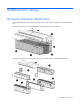
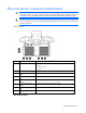
Item Component Description
1
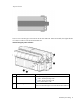
Canopy
The canopy has two 6.10 m (20 ft) parts that are installed on top of the HP
POD 240e NA.
2
Adiabatic units and
cradles
Each of the four cradles contain three Adiabatic units.
3
AHU service area end
walls
The HP POD 240e offers AHU service access in these two locations.
4
IT section A (primary
structure)
The IT section A (primary structure)
contains the ECS. Conditioned air passes
through the IT section A and IT section B structures to force cool air through the
IT equipment.
5
Hot aisle The hot aisle structure is a separate space where hot exhaust air from the
servers can be expelled out of the structure or recirculated. The HP POD 240e
isolates the IT sections from the hot aisle for efficiency.
6
IT section B (secondary
structure)
The IT section B (secondary structure) is similar to the IT section A (primary
structure), but IT section B does not contain the ECS.
IMPORTANT: You must consult with the AHJ to determine the egress requirements for the hot-aisle
service area that you must provide. Requirements might include landings and stairs to be installed
at both ends of the hot aisle service area for emergency egress.
Life safety component identification
Internal life safety components
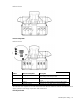
Top view shown
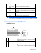
Item Component Description
1
Emergency switch locations There are six emergency switch boxes, one by each personnel access
door throughout the HP POD 240e NA. Each emergency switch box
includes items (2) and (3).
2
Fire alarm manual pull Enables manual initiation of the fire system, which includes the
activation of the interior and exterior fire strobe lights.
3
EPO button Disconnects the HP POD 240e NA from main power feeds and
activates the red EPO indicator light on the outside of the HP POD 240e
NA.
To reset the EPO button, switch the EPO to the Active position. Failure to
do so prevents the HP POD 240e NA from being able to restart.