
HP Performance Optimized Datacenter (POD) 240a Site Requirements Guide

Environmental considerations 19
WARNING: To avoid the risk of personal injury or electric shock, the HP POD 240a must be
properly grounded, and each of the individual sections must be bonded together per NFPA 70 in
accordance with NEC (NA) and IEC (EMEA and APJ).
CAUTION: You must remove any painted surface from all grounding surfaces. Failure to do so
results in an ineffective ground.
• Grounding and bonding of the HP POD 240a must comply with Article 250 of the NFPA 70 in
accordance with NEC (NA) and IEC (EMEA and APJ).
• The HP POD 240a structural sections, metal raceways, wireways, conduit, boxes, and other external
intersystem components must be bonded with grounding conductors per NFPA 70 in accordance with
NEC (NA) and IEC (EMEA and APJ).
• Bonding of Piping Systems and Exposed Structural Steel must comply with NFPA 70 in accordance with
NEC (NA) and IEC (EMEA and APJ).
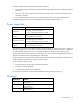
Feature Specification
Grounding electrode
conductor pad
•
A grounding pad is located on the underside of the HP POD 240a at the outside
corner of each IT section, under the electrical panel.
•
Grounding pads are located inside the HP POD 240a at ceiling level to bond the
sections together and bond the IT racks.
•
This point must be connected to the grounding system or building steel in
accordance with Article 250 of the NEC or equivalent regional regulation.
Grounding lugs
•
Grounding lugs cannot be attached to any painted surface.
•
Grounding lugs must be compression-type 2-hole lug
Ground rod system or
ground well
Customer must provide an effective grounding system with ground rod or ground well.
IMPORTANT: Before installing the HP POD 240a, consult your local AHJ for applicable codes
and to review site-specific location guidelines. If needed, obtain any necessary permits.
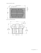
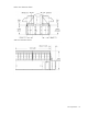
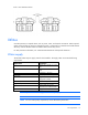
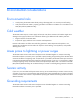
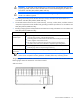
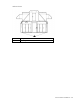
The grounding electrode conductor connections are located on IT sections A and B of the HP POD 240a. The
following figure shows the location for one of the IT sections.
Side view shown