
HP Performance Optimized Datacenter (POD) 240a Site Requirements Guide


Capacities 6
Capacities
Capacity limitations
The capacity limitations of the HP Performance Optimized Datacenter (POD) 240a includes two main
categories: electrical power capacity and mechanical cooling capacity. Both of these categories are
interdependent, and you must consider them in conjunction with the overall customer requirements.
The limiting capacity (electrical or mechanical cooling) is the overall limiting design factor and is used by HP
to develop the POD solution for our customer. For the purposes of the examples in this guide, (A & B) power
feeds are discrete for both main power feeds.
Electrical power capacities (Critical IT Load)
The IT electrical system of the HP POD 240a contains four main power feeds (A and B for both primary and
secondary sides). Each feed is rated at 800A 415VAC Wye 3-phase. The failure mode is the loss of either
main IT power busway. The electrical system yields the following possible IT loads:
• N = 2300 kW
• 2N = 1150 kW
Mechanical cooling capacities
The cooling system for the HP POD 240a consists of 24 DX cooling units. The incoming power connections
for the DX units are four 300A 480VAC, delta, 3-phase breakers. The cooling system yields a maximum
cooling capacity of:
N = 1347 kW
Power to the DX units is supplied through the associated main mechanical feed (mechanical A or mechanical
B, but not both). Because of this power availability limitation, the mode of failure for this system is the loss of
a power feed, which results in half of the DX units going offline. The resultant change in cooling capacity is:
N+0 = 674 kW
Currently, the electrical portion of the mechanical cooling systemis not redundant. However, the number of
DX units allowed to be online at maximum power can be reduced to enable backup DX units to be available.
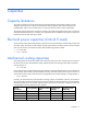
The following table shows the number of DX units held in reserve per IT section (N+1 requires two DX units
to be dormant) as well as maximum air flow possible.
DX unit
redundancy
DX units (quantity) Maximum air flow
(CFM)
Maximum rack
(quantity)
Air flow per rack
(CFM/rack)
N
24 156000 44 3545.5
N+1
22 143000 40 3575.0
N+2
20
130000
36
3611.1
N+3
18 117000 33 3545.5