HP Performance Optimized Datacenter (POD) Networking Guide Abstract This document provides networking guidance for the various PODs.
© Copyright 2011, 2012 Hewlett-Packard Development Company, L.P. The information contained herein is subject to change without notice. The only warranties for HP products and services are set forth in the express warranty statements accompanying such products and services. Nothing herein should be construed as constituting an additional warranty. HP shall not be liable for technical or editorial errors or omissions contained herein.
Contents Overview ..................................................................................................................................... 4 Networking introduction ............................................................................................................................. 4 Network best practices............................................................................................................................... 4 Planning considerations ..............................
Overview Networking introduction This guide is a primer and does not cover all networking best practices for the PODs. The customer has responsibility for providing the airflow direction of the network devices that are intended to be installed, especially if the devices are customer-furnished equipment. This must be managed by the account team and the network solution architect. Devices that require hot aisle servicing or maintenance must be placed in racks that allow full rear access.
• Where is the entry point for the Telecom panel? • Which hardware components are required for termination? • What is the hardware placement within the Telecom panel? • How many fiber/copper devices are being terminated? • What are the length of service loops within the Telecom panel? • Is hardware designed to be used only in racks? • Is this single or multi-homed? • Are the network specifications available? • Are site and network drawings available? If you require HP to provide an Externa
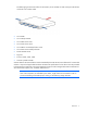
• Several of these previously listed devices have the potential of supporting up to 864 ports, which can result in a large volume of cables, and must be placed in a rack that has full rear-door access to facilitate the maintenance or the replacement of hardware. • The recessing of switches to be flush with the back of the rack will require the prevention of air flow recirculation to eliminate the mixing of hot aisle and IT section air.
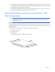
The following figure shows the airflow for the 3750-X, which includes air inlets on the port side and are not found in the 3750-E model.
Overview 8
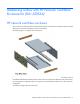
Addressing airflow with HP Network Switchbox Enclosure Kit (SKU AT053A) HP network switchbox enclosure Devices that are not optimized for front-to-back airflow require an HP Network Switchbox Enclosure Kit (SKU AT053A) which has been designed to alleviate overheating. The following figure is a diagram of the AT053A kit. During the design phase, the additional RU space required for the top and bottom of the enclosure must be considered.
AT053A Rack with two side to side air flow switches Item Component Description 1 Air baffle top The top of the air baffle that allows side air flow. 2 Air baffle bottom The bottom of the air baffle that allows side air flow. AT053A Rack with three side to side air flow switches Item Component Description 1 Air baffle top The top of the air baffle that allows side air flow. 2 Air baffle bottom The bottom of the air baffle that allows side air flow.
Devices that are installed in the HP Network Switch Enclosure and require more than 3RU of space will need additional side panels from the (HP Network Switch Enclosure Sidepanel Kit (SKU AT960A). The rack openings on the back side of the AT053A HP Network Switch Enclosure must be filled with blanking panels. Cisco MDS 9500 multilayer director This device requires 3RU minimum space below and above the chassis to provide air flow.
Cisco Catalyst 6500-E This device requires 2RU minimum space below and 3RU above the chassis. The device also requires a Network Switchbox Enclosure Kit (SKU AT053A) and an HP Network Switch Enclosure Side panel Kit (SKU AT960A). The Cisco Catalyst 6500-E does not require a side panel kit on the exhaust side of the chassis.
Cabling POD cable management The customer must create and finalize the POD network design and configuration to include point-to-point cabling specification prior to the receipt of the purchase order. The customer network solution architect will work with the HP account team network solution architect to finalize the POD network strategy. The following figure illustrates the rack dimensions that must be considered.
Feature Specification Quantity of cable tray sections over racks • • Dimensions of cable tray sections across the hot aisle 8 in wide x 2 in deep x 98 in long Quantity of cable tray sections across the hot aisle connecting the IT sections Three per HP POD 240a Four per rack aisle Eight total per HP POD 240a The following image illustrates the location of the cable tray in the hot aisle. The inset image illustrates how the cable tray hangs from the ceiling of the hot aisle.
The following images illustrate the cable tray. Integrating additional IT at the customer site When installing additional hardware in the POD on location, follow these guidelines: • Maintain hot and cold air separation within the racks. • PDUs in the POD are not equipped with L6-20 connectors. HP POD 240a In the HP POD 240a, avoid rack placement for network switches in racks 1 and 22.
Top view shown Item Component Description 1 Dock side The side of the HP POD 240a that provides direct access to IT section A, IT section B, and the hot aisle. 2 Truck/power side The side of the HP POD 240a that provides access to all main power components. HP POD 40c In the HP POD 40c, avoid rack placement for network switches in racks 1, 2, 5, 6, 7, 11, 12, 16, 17, 18, 21 and 22. HP POD 40c G2 In the HP POD 40c G2, avoid rack placement for network switches in racks 4, 8, 12, 16, and 20.
HP POD 20c In the HP POD 20c, avoid rack placement for network switches in racks 1, 5, 6, and 10.
Network access Network entry HP POD 240a The HP POD 240a has six network access points at the rear of the HP POD 240a above the cargo doors. NOTE: The connection portal location and configuration might look different, depending on the POD design. Rear cargo end view shown HP POD 40c and HP POD 20c The HP POD 40c and HP POD 20c have six network access penetrations in vertical alignment on the rear cargo door.
Rear cargo end view shown NOTE: The cargo doors might look different, depending on the POD design. The HP POD 40c G2 also has six network access penetrations in vertical alignment on the water connect side of the POD. Water connection end view shown The HP POD 40c G2 also has a single network access penetration on the water connect side of the POD.
Water connection end view shown Network demarcation Network configurations vary; therefore, the customer is responsible for installing external telecom panel access. The POD does not ship with an external telecom panel to serve as a demarcation point of entry into the POD. Therefore, customers must specify the appropriate external telecom panel. An external telecom panel is not required to extend network cables from outside the POD.
POD external telecom panel example The external telecom panel model can be applied to any HP POD version as long as the size, rating, cable count capacity, and mounting location requirements are met.
Frequently asked questions 1. Can a customer use mounting ear brackets on the equipment in the racks in the POD? When installing through the front of the rack (IT section), yes. If equipment must be installed from the back of the rack (hot aisle), HP recommends rail kits instead of mounting ear brackets for devices to be used in the racks. The customer must ensure that rail kits are available for the third-party equipment that is ordered from their respective vendor.
Documentation feedback HP is committed to providing documentation that meets your needs. To help us improve the documentation, send any errors, suggestions, or comments to Documentation Feedback (mailto:docsfeedback@hp.com). Include the document title and part number, version number, or the URL when submitting your feedback.