
3.0/4.0 dBi Dual-Band 3-Element MIMO Omni Directional Antenna (J9171A) Guide v5.5.0

2 HP 3.0/4.0 dBi Dual-Band 3-Element MIMO Omni Directional Antenna (J9171A) Guide
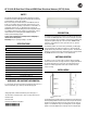
then mount the antenna to the clips, as illustrated in Figure 2. For 9/16”
rectangular profile grid, install the supplied clips in the same manner.
ANTENNA PORTS
Antenna cable port identification is as follows:
• Red = End port
• Green = Center port
• Blue = End port
Respect color coding when connecting to the access point (AP).
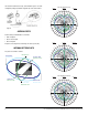
ANTENNA PATTERN PLOTS
The plots are oriented as follows:
Figure 2
Plot Orientation Diagram
E0 Plane 270°
E0 Plane 90°
H Plane 0°
E90 Plane 90°
H Plane 90°
E90 Plane 0°
H Plane 180°
E90 Plane 270°
E0 Plane 180°
E0 Plane 0°
E90 Plane 180°
H Plane 270°
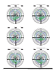
0
350
340
330
320
310
300
290
280
270
260
250
240
230
220
210
200
190
180
170
160
150
140
130
120
110
100
90
80
70
60
50
40
30
20
10
-20 -10 0
dB
2.45 GHz Red Port (End)
H Plane E0 Plane E90 Plane
0
350
340
330
320
310
300
290
280
270
260
250
240
230
220
210
200
190
180
170
160
150
140
130
120
110
100
90
80
70
60
50
40
30
20
10
-20 -10 0
dB
2.45 GHz Blue Port (End)
H Plane E0 Plane E90 Plane
0
350
340
330
320
310
300
290
280
270
260
250
240
230
220
210
200
190
180
170
160
150
140
130
120
110
100
90
80
70
60
50
40
30
20
10
-20 -10 0
dB
2.45 GHz Green Port (Center)
H Plane E0 Plane E90 Plane